Spinal implant locking member with improved guidance, tactile and visual feedback

a technology of pinal implants and locking members, applied in the field of pinal implants having and a lock aid, can solve the problems of cap difficulty in engaging in the tulip or receiver, cross thread failure upon initial thread engagement, and exacerbated problems

Active Publication Date: 2011-06-23
X SPINE SYST
View PDF23 Cites 35 Cited by
  • Summary
  • Abstract
  • Description
  • Claims
  • Application Information

AI Technical Summary

Benefits of technology

[0018]In one aspect, one embodiment comprises an implant comprising a receiver having at least one internal wall defining a bore, at least a portion of the receiver having a receiver thread, the receiver further comprising a rod-receiving channel in communication with the bore, the rod-receiving channel being adapted to receive a rod, a polyaxial screw for receipt in the bore, a cap having a cap thread for mating with the receiver thread to permit the cap to be screwed on the receiver in order to lock the rod in the rod-receiving channel of the receiver, and a lock aid associated with at least one of the receiver or the cap for facilitating providing at least one of a tactile feedback when the cap is mounted on the receiver, a visual feedback for facilitating mounting the cap on th...

Problems solved by technology

Therefore, the threads of the locking cap and tulip must bear high torque loading which can result in cross-threading and/or thread failure upon initial thread engagement.
Furthermore, the cap may be difficult to engage in the tulip or receiver under such conditions because the thread start-point of both the male and female threads are difficult to identify in a surgical environment.
These p...

Method used


Image

  • Spinal implant locking member with improved guidance, tactile and visual feedback
  • Spinal implant locking member with improved guidance, tactile and visual feedback
  • Spinal implant locking member with improved guidance, tactile and visual feedback

Examples


Embodiment Construction

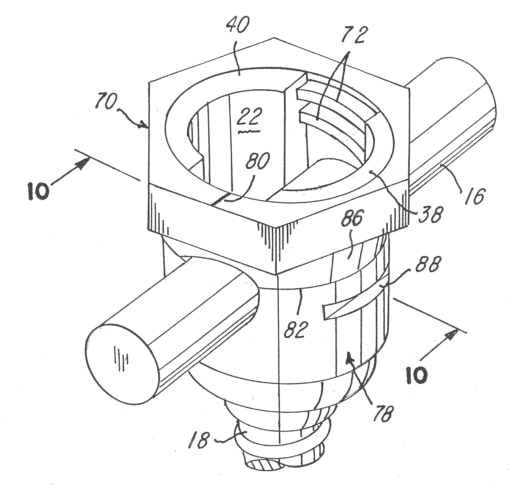
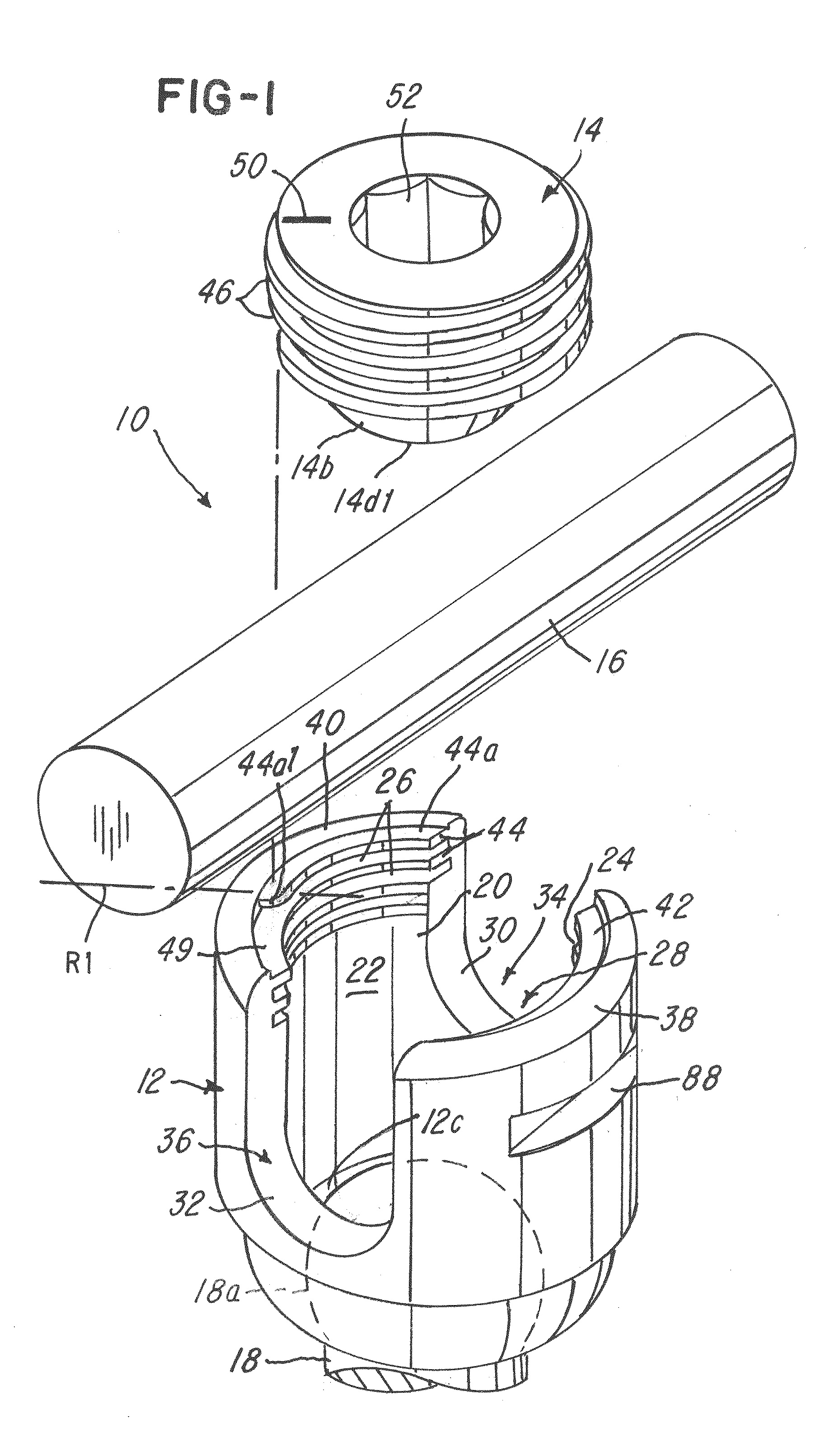
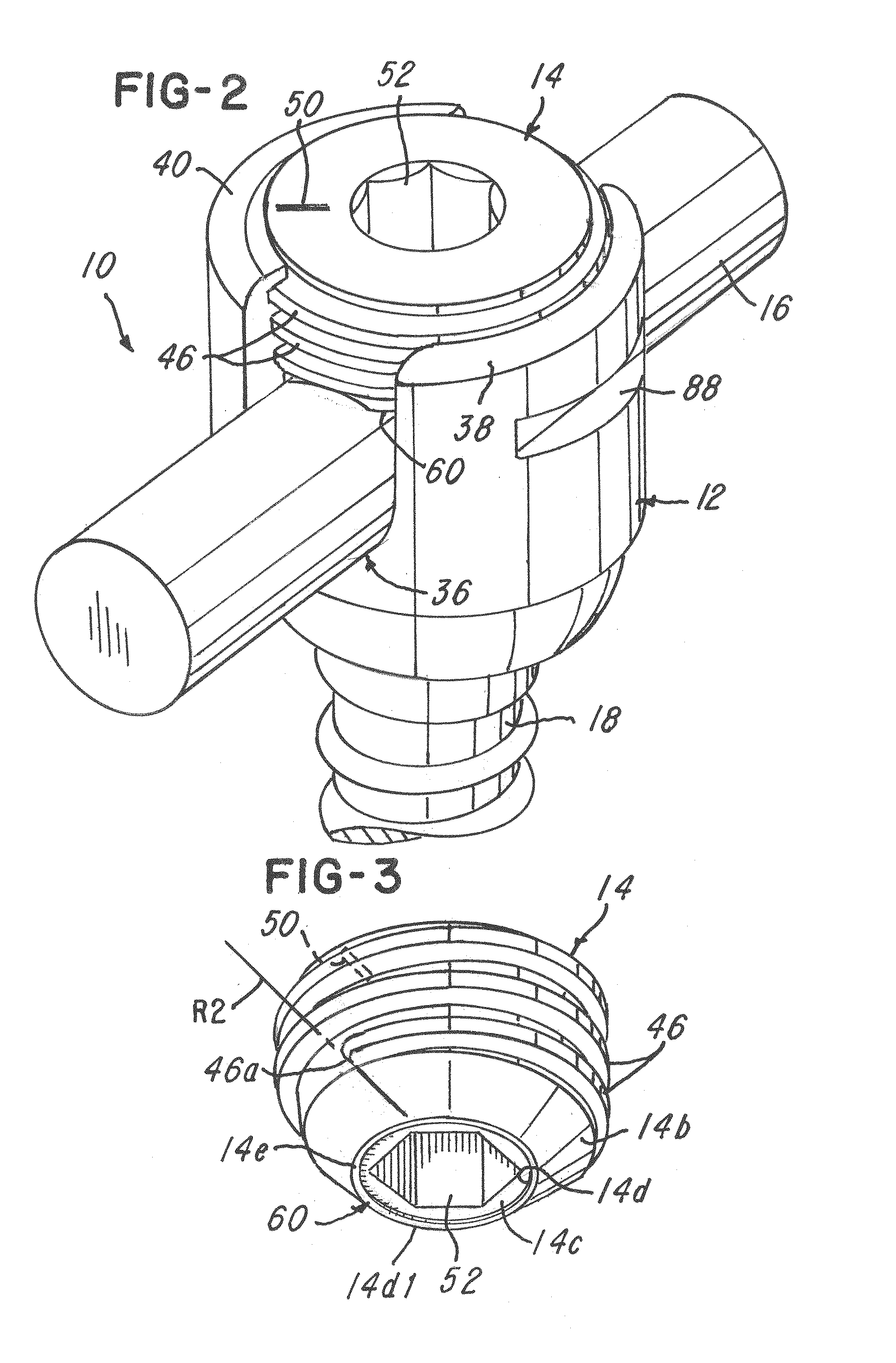
[0034]Referring now to FIGS. 1-10, an implant, polyaxial screw, system and method 10 are shown. In a first illustrative embodiment, the system 10 comprises a receiver 12 and a cap 14 which is threadably mounted on the tulip or receiver 12. The receiver 12 receives the cap 14 after a rod 16 and a polyaxial screw 18 are received in the receiver 12 in a manner conventionally known and as shown in FIG. 1.

[0035]The receiver 12 comprises at least one internal wall 20 defining a bore 22. At least a portion of the receiver 12 comprises a plurality of female threads, such as threads 24 and 26. In this regard, note that the receiver 12 comprises a rod-receiving channel 28. The receiver 12 comprises a first generally U-shaped wall 30 that defines a first rod-receiving opening 34 and a generally opposed second generally U-shaped wall 32 that defines a second rod-receiving opening 36 as shown. The first and second rod-receiving openings 34 and 36 cooperate to define the rod-receiving channel 28 ...


PUM


Abstract

An implant having a receiver that is adapted to receive a polyaxial screw in the bore and either an internal or external cap. The cap can be an external or internal cap and the implant further has at least one locking aid in the form of at least one of a tactile feedback, a visual feedback or an enhanced fixation between the cap and a rod that is received in the receiver.

Description

BACKGROUND OF THE INVENTION[0001]1. Field of the Invention[0002]This invention relates to a spinal implant system and method and, more particularly, to an implant having and a lock aid that provides at least one of improved guidance, tactile or visual feedback or enhanced fixation and locking of a cap in a receiver of the implant.[0003]2. Description of the Related Art[0004]Spinal implant screws, such as those used in the pedicles of the thoracic and lumbar spines are commonly used today by spinal surgeons. In a typical prior art screw, there are three main components: a screw shaft, a polyaxial tulip head or receiver incorporating a female thread, and a locking cap incorporating a male thread. The purpose of the threaded locking cap is to affix a spinal stabilizing element, typically a cylindrical rod, to the screw assembly.[0005]During the surgical procedure the surgeon must forcefully seat the rod into the tulip via rotation of the locking cap. Such seating affects the desired co...

Claims


Application Information

Patent Timeline
IPC IPC(8): A61B17/86A61B17/00
CPCA61B17/7037A61B17/7032A61B17/8665A61B2017/567A61B2017/681A61B2017/8675A61B2017/868
Inventor KIRSCHMAN, DAVID LOUIS
Owner X SPINE SYST
Why Eureka
Try Eureka