Robot system, and control apparatus and method thereof

a robot and control apparatus technology, applied in the field of robot systems, can solve the problems of increasing cycle time, difficult to complete the operation (conveyance), and deviating position and orientation of the operation target, and achieve the effect of not increasing the cycle tim

Active Publication Date: 2011-06-23
CANON KK
View PDF8 Cites 60 Cited by
  • Summary
  • Abstract
  • Description
  • Claims
  • Application Information

AI Technical Summary

Benefits of technology

[0015]The present invention is directed to performing position and orientation measurement, and position and orientation correction of an operation target grasped by a hand without increasing the cycle time.

Problems solved by technology

However, unless the operation target (part) is correctly arranged on the parts supply pellet in a predetermined position and orientation, the part will not be completely grasped, which can make it difficult to complete the operation (conveyance).
However, even when the operation target is grasped while taking such a measure, the position and orientation of the operation target can deviate due to contact between the grasping mechanism of the hand and the operation target.
However, in Japanese Patent Application Laid-Open No. 2009-50921, there is the problem that cycle time increases when measuring the position and orientation of the grasped operation target, because the operation target is made to hit an object having a known position and orientation.
Therefore, there is the problem that when performing a fitting or assembly operation on another operation target, the positional deviation of another operation target cannot be corrected.
Moreover, the above-described conventional art suffers from the problems that when the positional deviation of the grasped target is large, the target may collide with an obstruction while the arm is being moved, or that the grasping operation may have to be performed again.

Method used


Image

  • Robot system, and control apparatus and method thereof
  • Robot system, and control apparatus and method thereof
  • Robot system, and control apparatus and method thereof

Examples


Embodiment Construction

[0031]Various exemplary embodiments, features, and aspects of the invention will be described in detail below with reference to the drawings.

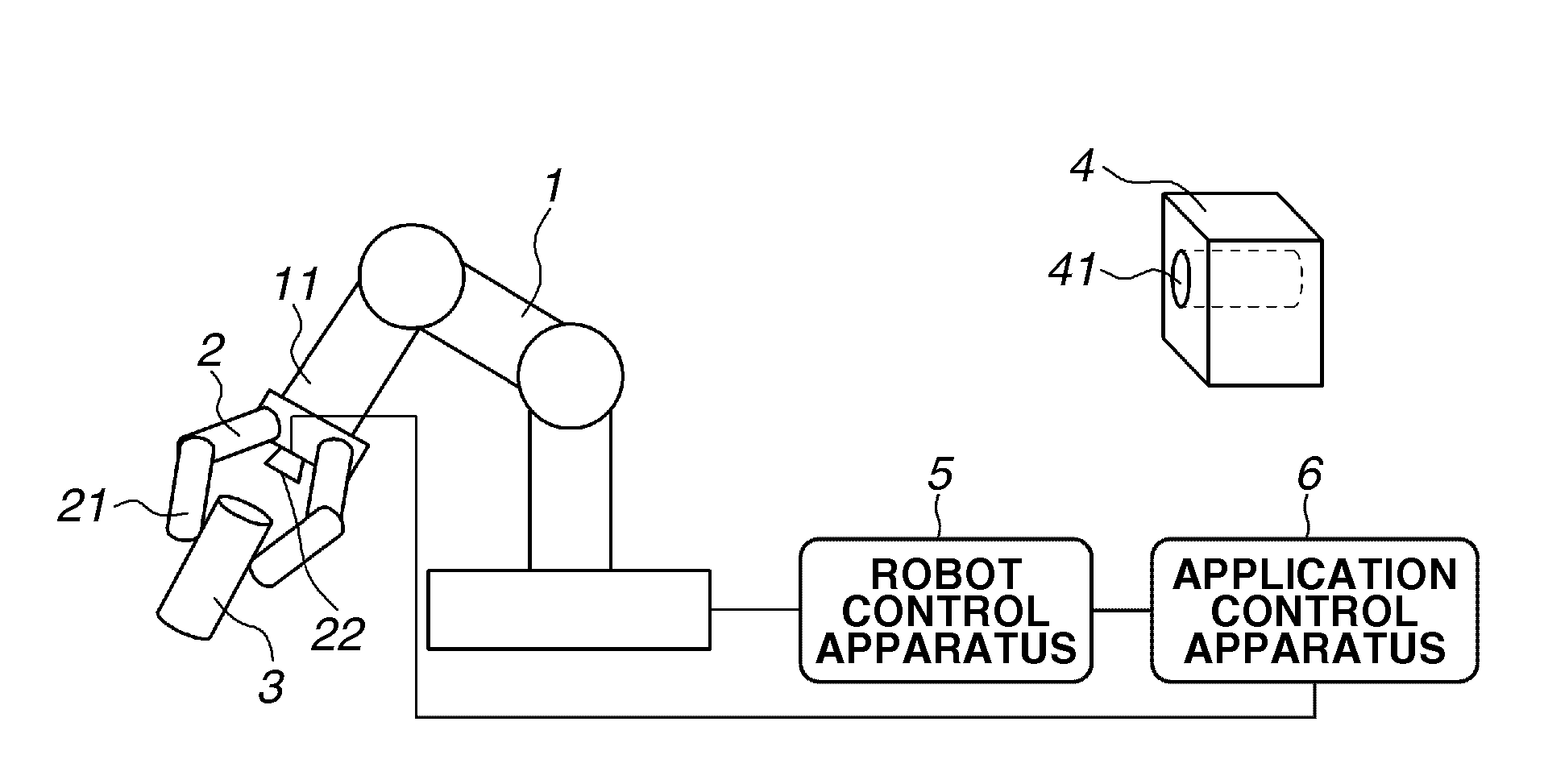
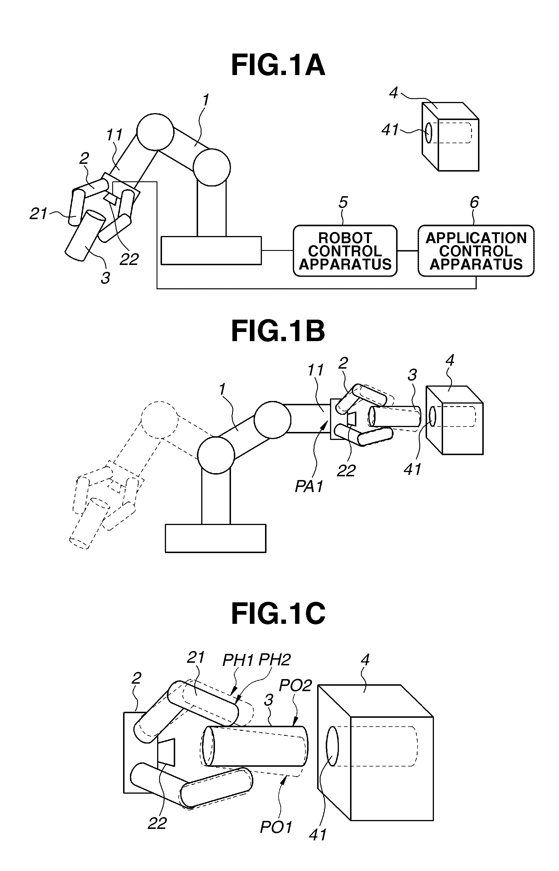
[0032]FIG. 1A illustrates a configuration example of a robot system according to a first exemplary embodiment in which the present invention is applied. An arm 1 is an articulated serial-link robot. Each joint is driven by a motor, which enables the position and orientation of an arm tip portion 11 to be controlled.

[0033]A hand 2 is attached to the arm tip portion 11. The hand 2 has a grasping member (grasping mechanism) 21, which grasps and releases an operation target 3. Further, the hand 2 includes a control mechanism, such as a rotation mechanism and a multijointed finger mechanism, at a joint corresponding to a wrist, in a range that is sufficient for correction of the position and orientation of the grasped object. This mechanism can be realized even by, for example, a parallel ring mechanism, or a structure that combines an XYZ stage and...


PUM


Abstract

A robot system, including an arm capable of controlling a position and orientation of an arm tip portion, a hand, which is attached to the arm tip portion and which includes a grasping mechanism configured to grasp an operation target, capable of controlling a relative position and orientation from the arm tip portion of the grasped operation target, and a position and orientation measurement apparatus configured to perform relative position and orientation measurement from the arm tip portion of the grasped operation target, wherein measurement of the relative position and orientation from the arm tip portion of the operation target is performed after the operation target is grasped by the grasping mechanism, while the arm tip portion is still moving, and correction of the relative position and orientation from the arm tip portion of the hand is performed based on a result of the position and orientation measurement so that the arm tip portion takes a predetermined relative position and orientation from the arm tip portion.

Description

BACKGROUND OF THE INVENTION[0001]1. Field of the Invention[0002]The present invention relates to a robot system for grasping and moving an operation target, and a control apparatus, method, and program thereof.[0003]2. Description of the Related Art[0004]Industrial robots have been introduced into production sites for various purposes, such as to stably produce high-quality products, and to release people from dangerous operations and operations that cause fatigue.[0005]Conventionally, simple, repetitive tasks have been performed by attaching a hand for grasping an operation target on an arm of the robot, moving the arm along a predetermined course, and making the hand perform a grasping operation. Examples of simple tasks include the conveyance and sorting of operation targets, and the fitting and assembly with other operation targets.[0006]For instance, the conveyance of a part is used as an example. Since the part is placed on a predetermined position on a parts supply pellet, fi...

Claims


Application Information

Patent Timeline
Patent Type & Authority Applications(United States)
IPC IPC(8): G06F19/00
CPCB25J9/1687B25J9/1664B25J15/10B25J9/1676G05B2219/36504G05B2219/39487B25J9/1612B25J13/02B25J9/1666B25J15/00G05B2219/40032G05B2219/40082G05B2219/39568
Inventor NORO, HIDEO
Owner CANON KK
Why Eureka
Try Eureka