
System and method for area coverage using sector decomposition

a technology of sector decomposition and area coverage, applied in the field of navigation, can solve the problems of inefficiency of systems and cost prohibitiveness

Active Publication Date: 2011-06-23
DEERE & CO
View PDF91 Cites 78 Cited by
  • Summary
  • Abstract
  • Description
  • Claims
  • Application Information

AI Technical Summary

Benefits of technology

[0005]The different illustrative embodiments further provide a method for executing an area coverage path plan using sector decomposition. An expected width of a landmark is determined in pixels for a desired distance away from the landmark. An image having the landmark is identified. An observed width of the landmark is determined using the image. The observed width of the landmark is compared to the expected width of the landmark. A message is sent to a vehicle control process to move an autonomous vehicle bas...

Problems solved by technology

These systems tend to be inefficient and are often cost-prohibitive.

Method used


Image

  • System and method for area coverage using sector decomposition
  • System and method for area coverage using sector decomposition
  • System and method for area coverage using sector decomposition

Examples


Embodiment Construction

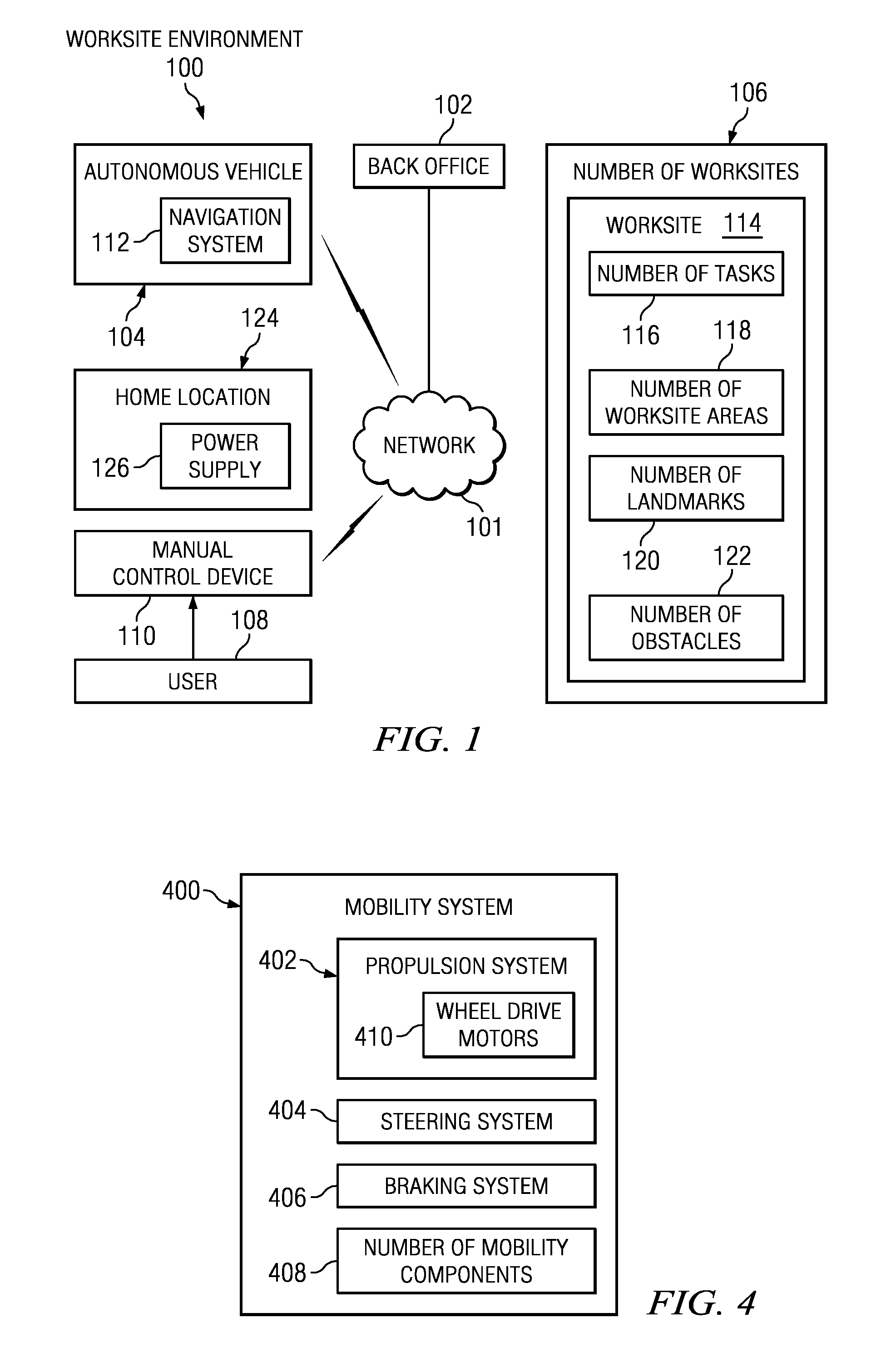
[0021]With reference to the figures and in particular with reference to FIG. 1, a block diagram of a worksite environment is depicted in which an illustrative embodiment may be implemented. Worksite environment 100 may be any type of worksite environment in which an autonomous vehicle can operate. In an illustrative example, worksite environment 100 may be a structure, building, worksite, area, yard, golf course, indoor environment, outdoor environment, different area, change in the needs of a user, and / or any other suitable worksite environment or combination of worksite environments.

[0022]As an illustrative example, a change in the needs of a user may include, without limitation, a user moving from an old location to a new location and operating an autonomous vehicle in the yard of the new location, which is different than the yard of the old location. As another illustrative example, a different area may include, without limitation, operating an autonomous vehicle in both an indo...


PUM


Abstract

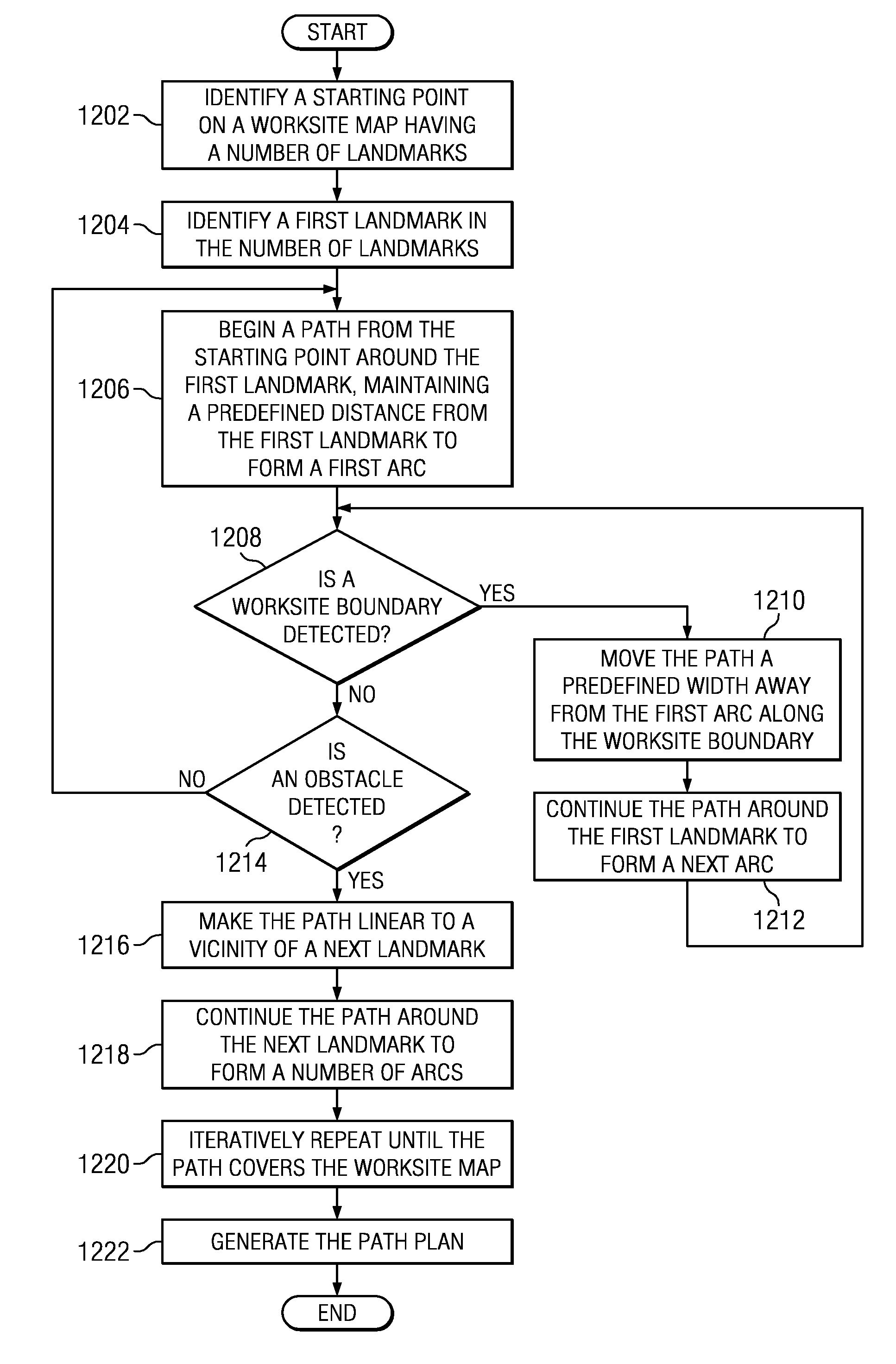
The different illustrative embodiments provide a method for generating an area coverage path plan using sector decomposition. A starting point is identified on a worksite map having a number of landmarks. A first landmark in the number of landmarks is identified. A path is generated around the first landmark until an obstacle is detected. In response to detecting the obstacle, the path is made linear to a next landmark. The path is generated around the next landmark.

Description

CROSS REFERENCE TO RELATED APPLICATIONS [0001]This application is related to commonly assigned and co-pending U.S. patent application Ser. No. ______ (Attorney Docket No. 18885-US) entitled “System and Method for Deploying Portable Landmarks”; U.S. patent application Ser. No. ______ (Attorney Docket No. 18886-US) entitled “Enhanced Visual Landmark for Localization” all of which are hereby incorporated by reference.FIELD OF THE INVENTION [0002]The present invention relates generally to systems and methods for navigation and more particularly to systems and methods for mobile robotic navigation. Still more specifically, the present disclosure relates to a method and system for area coverage using sector decomposition.BACKGROUND OF THE INVENTION[0003]The use of robotic devices to perform physical tasks has increased in recent years. Mobile robotic devices can be used to perform a variety of different tasks. These mobile devices may operate in semi-autonomous or fully autonomous modes. ...

Claims


Application Information

Patent Timeline
IPC IPC(8): G01C21/00G05D1/00G06F7/00G06K9/00H04N7/18
CPCG05D1/0219G05D1/0227G05D1/0246G05D1/0251G05D1/0255G05D1/0259G06K9/00664G05D1/027G05D1/0272G05D1/0274G05D2201/0208G05D2201/0215G05D1/0265G06V20/10
Inventor ANDERSON, NOEL WAYNE
Owner DEERE & CO
Learn More