Robot path planning method and system based on improved artificial potential field method

An artificial potential field method and path planning technology, applied to control/regulation systems, instruments, motor vehicles, etc., can solve problems such as poor versatility, poor environmental adaptability, and inability to solve static potential field problems

Active Publication Date: 2016-06-01
重庆科知源科技有限公司
View PDF4 Cites 63 Cited by
  • Summary
  • Abstract
  • Description
  • Claims
  • Application Information

AI Technical Summary

Problems solved by technology

The virtual water flow method has a certain effect in solving the local minimum point problem in the environment, but the algorithm efficiency is not high
The method of introducing the internal subject state successfully solves the local minimum problem in complex environments, but it c

Method used


Image

  • Robot path planning method and system based on improved artificial potential field method
  • Robot path planning method and system based on improved artificial potential field method
  • Robot path planning method and system based on improved artificial potential field method

Examples


Embodiment 1

[0109] The robot path planning method based on the improved artificial potential field method provided in this embodiment,

[0110] This embodiment provides a robot path planning method based on the improved artificial potential field method, comprising the following steps:

[0111] S1: Obtain the initial state parameters, environmental information and final target point of the robot;

[0112] S2: Obtain the current coordinate position and local target point of the robot;

[0113] S3: Establish the artificial potential field method based on the time virtual driving force to generate the reachable path between the current coordinate position of the robot and the local target point;

[0114] S4: Control the robot to travel along the reachable path;

[0115] S5: Detect whether the current coordinate position of the robot reaches the local target point within the visible range of the laser radar, if not, return to step S4 and continue to control the driving of the robot;

[011...

Embodiment 2

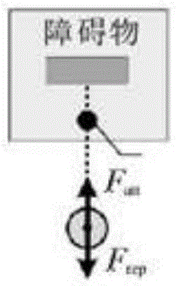
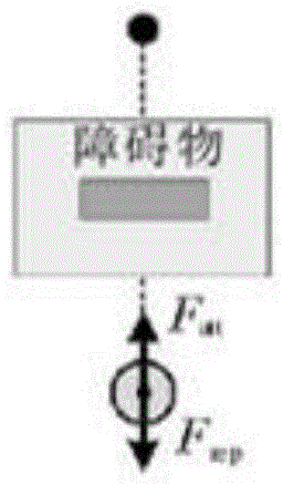
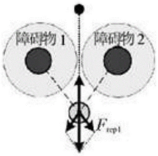
[0194] There are three scenarios in which local minimums will occur in robot path planning based on the artificial potential field method: Figure 1a -c is a schematic diagram of a local minimum scenario in robot path planning based on the artificial potential field method provided in this embodiment; Figure 1a The first common situation in which the robot provided by this embodiment falls into a local minimum (the target is between the obstacle and the robot); the box in the figure indicates the range of influence of the obstacle, the dot in the box indicates the target, and the circle outside the box for the robot; Figure 1b The second common situation in which the robot provided by this embodiment falls into a local minimum (obstacles are between the target and the robot); the box in the figure indicates the range of influence of the obstacle, the dot above the box indicates the target, and the circle outside the box for the robot; Figure 1c The third common situation in...

Embodiment 3

[0251] See flow chart Figure 4 , the technical solution in the embodiment of the present invention will be fully described below in conjunction with the flow chart.

[0252] Step 1: Take the robot's perspective at the starting point as the benchmark for the entire path planning, and establish a plane Cartesian coordinate system (the front of the robot's perspective is the y-axis, and the right-hand side is the x-axis).

[0253] Step 2: Use the inertial navigation system to obtain the initialization state S of the robot at the starting point 0 (including the Cartesian coordinates of the robot position (x 0 ,y 0 )=(0,0), the attitude angle θ of the current robot relative to the initial position 0 = 0° and the current robot speed v 0 =0).

[0254] Step 3: Use the single-line lidar sensor to obtain environmental information, including obstacle information in the environment. And set the Cartesian coordinates of the final target point in the robot control system (x g ,y g ...


PUM


Abstract

The invention discloses a robot path planning method and system based on an improved artificial potential field method, and the method comprises the steps: firstly finding local target points in a visual scope of a laser radar; secondly planning a reachable path from the current position of a robot to the local target points; and finally controlling and driving the robot to move to circularly detect the local target points till the robot reaches a final target point. The method employs the artificial potential field method to plan the path of the robot, solves a problem of a local minimal point appearing in path planning through a conventional artificial potential field method, and improves the conventional artificial potential field method, i.e., improving a gravitational potential function. Meanwhile, the method enables the whole task to be divided into a plurality of local target points, thereby achieving the optimal path. The method improves the instantaneity of path planning, environmental suitability and efficiency.

Description

technical field [0001] The invention relates to the field of local navigation of robots and intelligent vehicles, in particular to a robot path planning method based on an improved artificial potential field method. Background technique [0002] Real-time path planning and navigation of mobile robots is one of the key elements reflecting the robot's autonomous ability, and it is also one of the more difficult problems to solve. Robot path planning is mainly divided into planning with known environmental information and planning with unknown environmental information. For the former, offline planning is mostly used, and the obtained path is better, while the latter mostly uses online planning, which reflects the real-time nature of path planning. [0003] In recent years, many methods of path planning for mobile robots have been studied. The main path planning methods can be divided into two categories: artificial intelligence methods (AI) and artificial potential field met...

Claims


Application Information

Patent Timeline
IPC IPC(8): G05D1/02
CPCG05D1/0217G05D2201/0217
Inventor 孙棣华廖孝勇赵敏杜道轶
Owner 重庆科知源科技有限公司
Why Eureka
Try Eureka