Fiber Identification Using Mode Field Diameter Profile

a fiber identification and mode field technology, applied in the field of fiber identification using mode field diameter profile, can solve the problems of prone to human error in conventional identification and verification of specific fibers within a network, costly faults or failures in fibers,

Active Publication Date: 2011-06-23
AT&T INTPROP I L P
View PDF3 Cites 29 Cited by
  • Summary
  • Abstract
  • Description
  • Claims
  • Application Information

AI Technical Summary

Problems solved by technology

Faults or failures in the fiber may be costly, in terms of repairing the fiber, as well as any adverse affects in service (e.g., disruption or loss of service).
However, conventional identification and verification of specific fibers within a network are prone to human error.

Method used


Image

  • Fiber Identification Using Mode Field Diameter Profile
  • Fiber Identification Using Mode Field Diameter Profile
  • Fiber Identification Using Mode Field Diameter Profile

Examples


Embodiment Construction

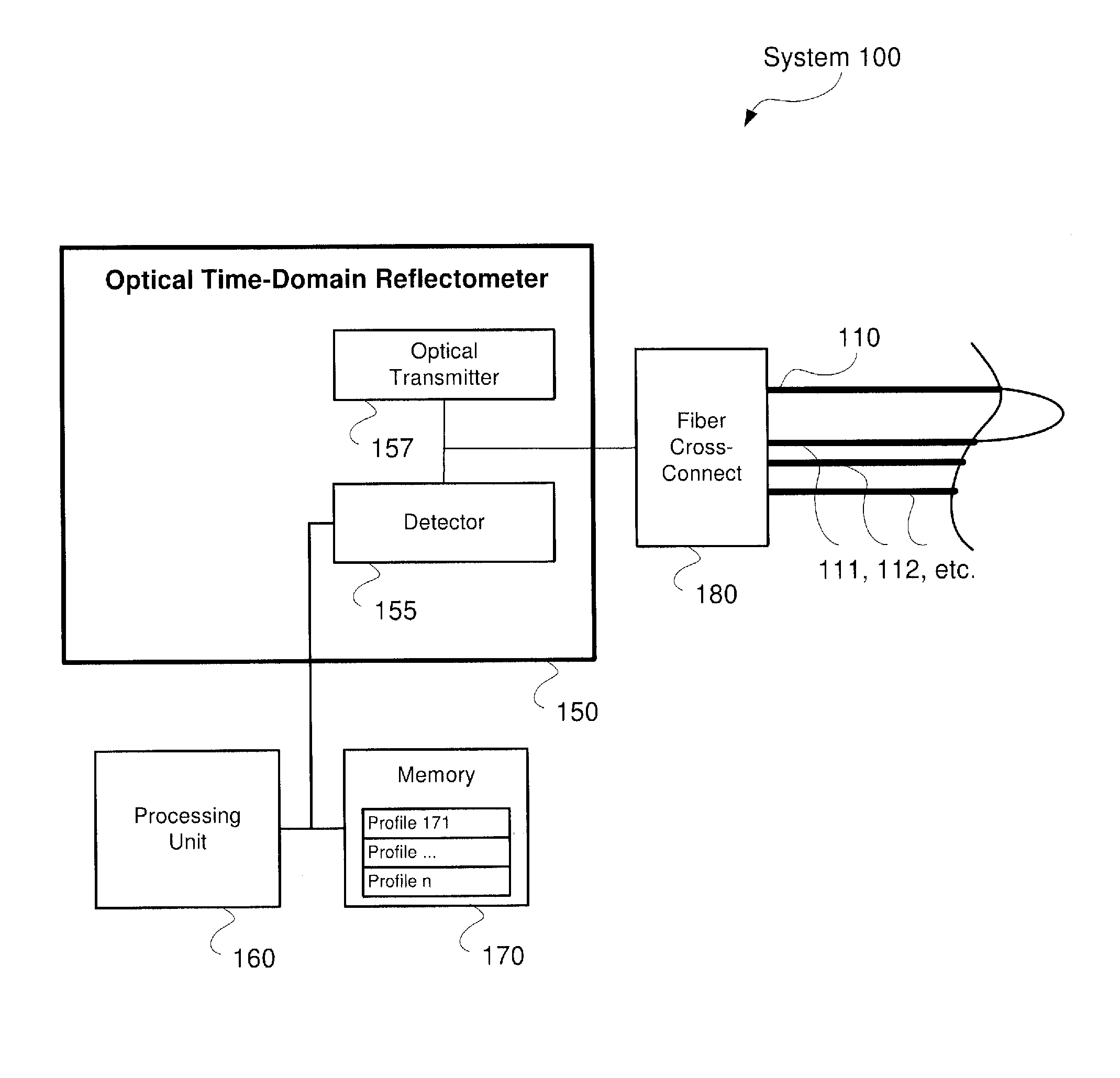
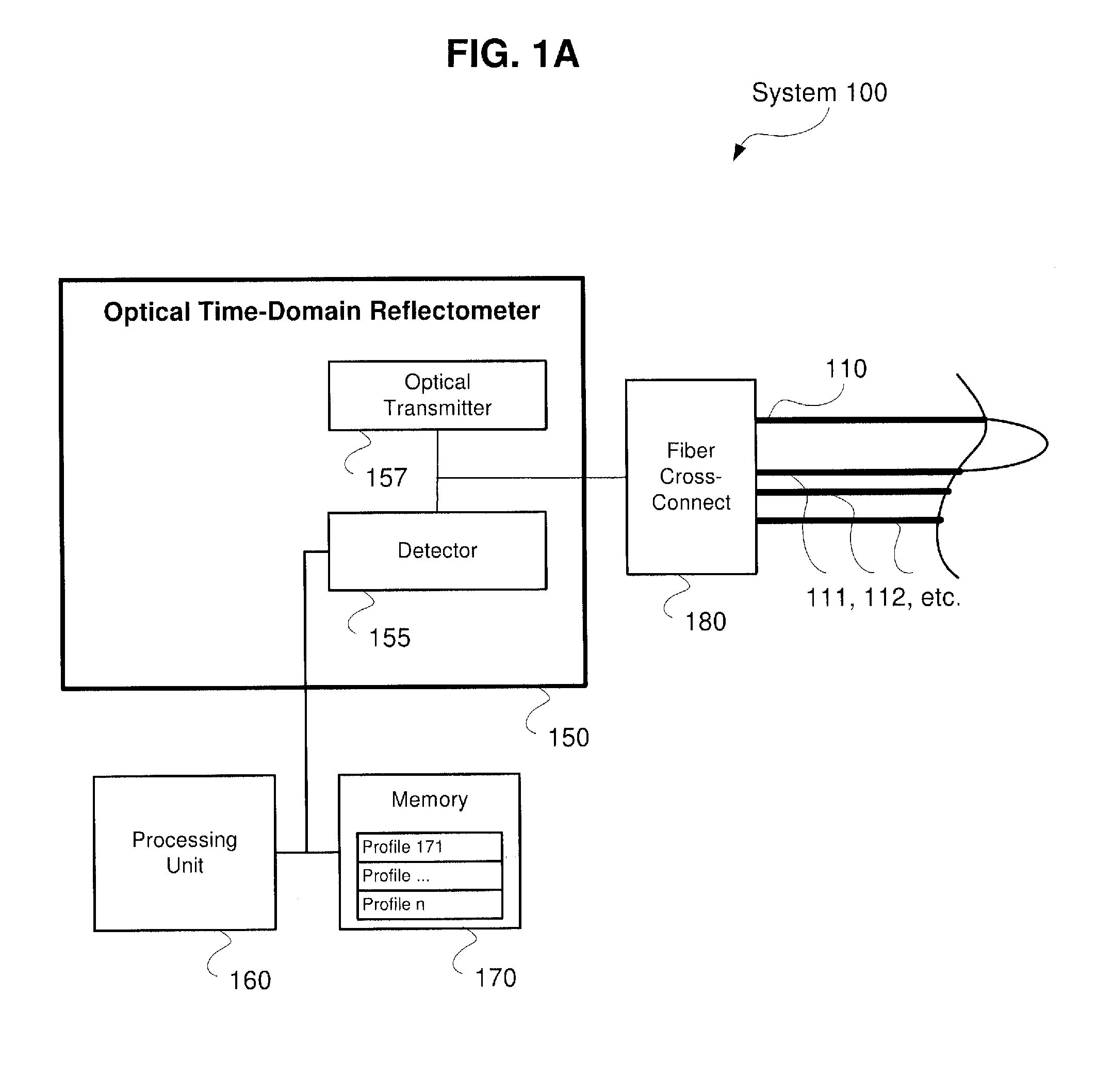
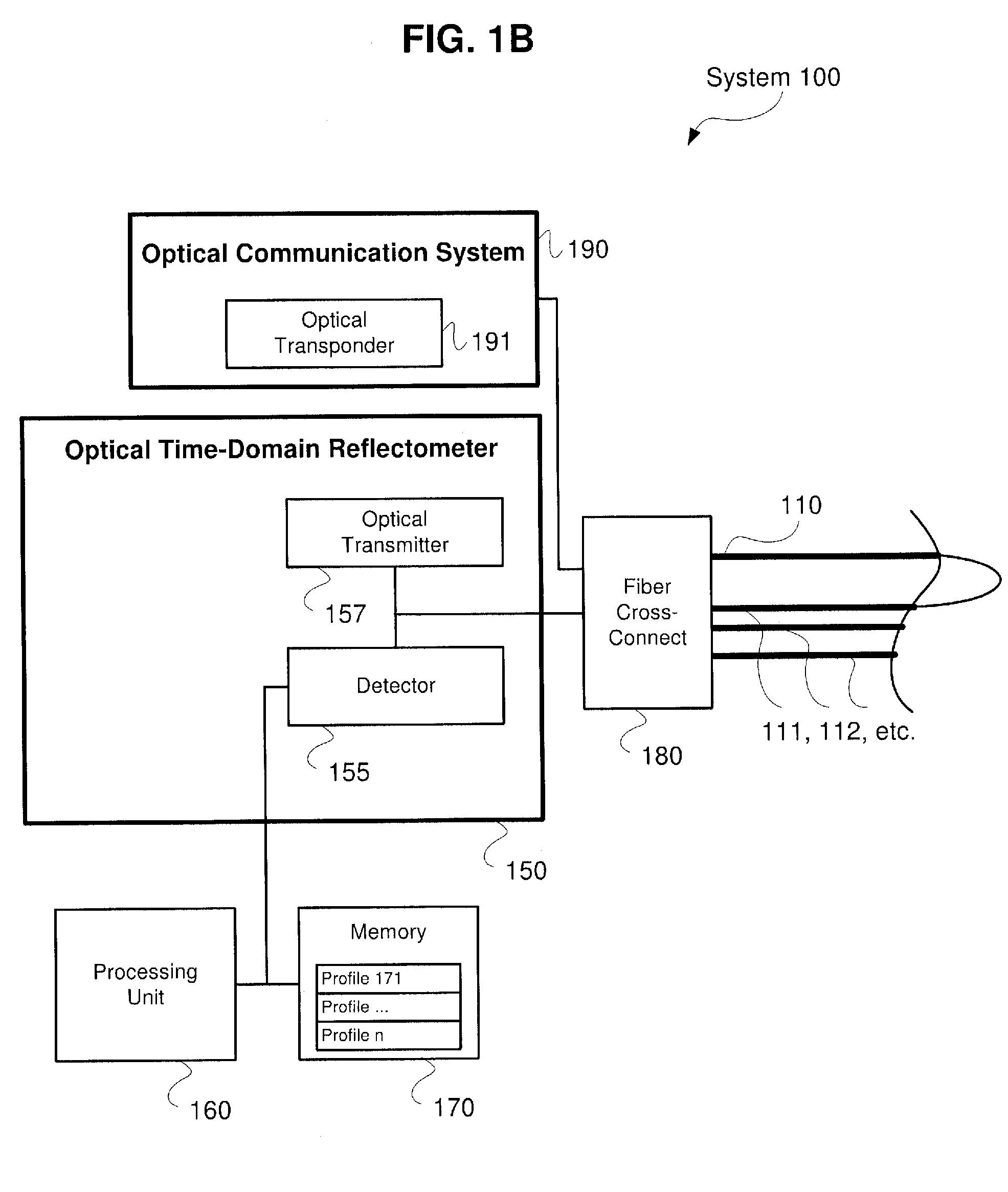
[0008]The exemplary embodiments may be further understood with reference to the following description and the related appended drawings, wherein like elements are provided with the same reference numerals. The exemplary embodiments are related to systems and methods for uniquely identifying, or “fingerprinting,” optical fibers based upon measurements from an optical time-domain reflectometer (“OTDR”). These measurements may include various characteristics of the tested fiber, such as the relative backscatter, which may be described as a measure of the variation in the mode field diameter (“MFD”) of the fiber. It should be noted that within the field of fiber optics, a MFD reading may be defined as an expression of distribution of the irradiance, or the optical power per unit area, across an end face of a tested fiber.

[0009]Conventional identification of a particular fiber within a network office has been accomplished by tracing fiber jumpers. Furthermore, these conventional methods ...


PUM


Abstract

Described herein are systems and methods for uniquely identifying, or “fingerprinting,” optical fibers based upon measurements from an optical time-domain reflectometer (“OTDR”). One embodiment of the disclosure of this application is related to a computer readable storage medium including a set of instructions that are executable by a processor. The set of instructions being operable to retrieve a profile for an intended fiber, the profile including unique measurement data of the intended fiber, collect further measurement data from a connected fiber within a network, compare the unique measurement data of the intended fiber to the further measurement data of the connected fiber, and confirm an identity of the connected fiber as being the intended fiber when the unique measurement data matches the further measurement data, and trigger an alert when the unique measurement data does not match the further measurement data.

Description

BACKGROUND[0001]An optical time-domain reflectometer (“OTDR”) is an opto-electronic instrument used to characterize an optical fiber. A typical OTDR injects a series of optical pulses into the fiber during a testing process. From the same end of the fiber, the OTDR also extracts light that is scattered and reflected back from points in the fiber due to irregularities in the optical fiber structure. This process is equivalent to the manner in which an electronic time-domain reflectometer may measure reflections caused by changes in the impedance of the cable under test. Accordingly, the strength of the back-reflected light is measured and integrated as a function of time, and is plotted as a function of fiber length.[0002]OTDRs have conventionally been standard equipment for the characterization of optical fiber. Specifically, it is well known that by transmitting a pulse down a fiber and analyzing the back-reflected light, the loss of the fiber may then be characterized. OTDRs may c...

Claims


Application Information

Patent Timeline
Patent Type & Authority Applications(United States)
IPC IPC(8): G06N5/02
CPCG01M11/3136H04B10/071G01M11/3145
Inventor NAGEL, JONATHANWOODWARD, SHERYL
Owner AT&T INTPROP I L P
Why Eureka
Try Eureka