Heat exchanger and water heater incorporating the same

Inactive Publication Date: 2011-06-30
NORITZ CORP
View PDF15 Cites 29 Cited by
  • Summary
  • Abstract
  • Description
  • Claims
  • Application Information

AI Technical Summary

Benefits of technology

[0009]It is an object of the present invention to provide a heat exchanger capable of appropriately pr

Problems solved by technology

The upper wall portion 90d thus heated to such high temperatures dissipates heat in

Method used


Image

  • Heat exchanger and water heater incorporating the same
  • Heat exchanger and water heater incorporating the same
  • Heat exchanger and water heater incorporating the same

Examples


Embodiment Construction

[0043]Hereinafter, preferred embodiments of the present invention will be described specifically with reference to the drawings.

[0044]FIGS. 1 to 5 illustrate one exemplary water heater incorporating a heat exchanger according to the present invention.

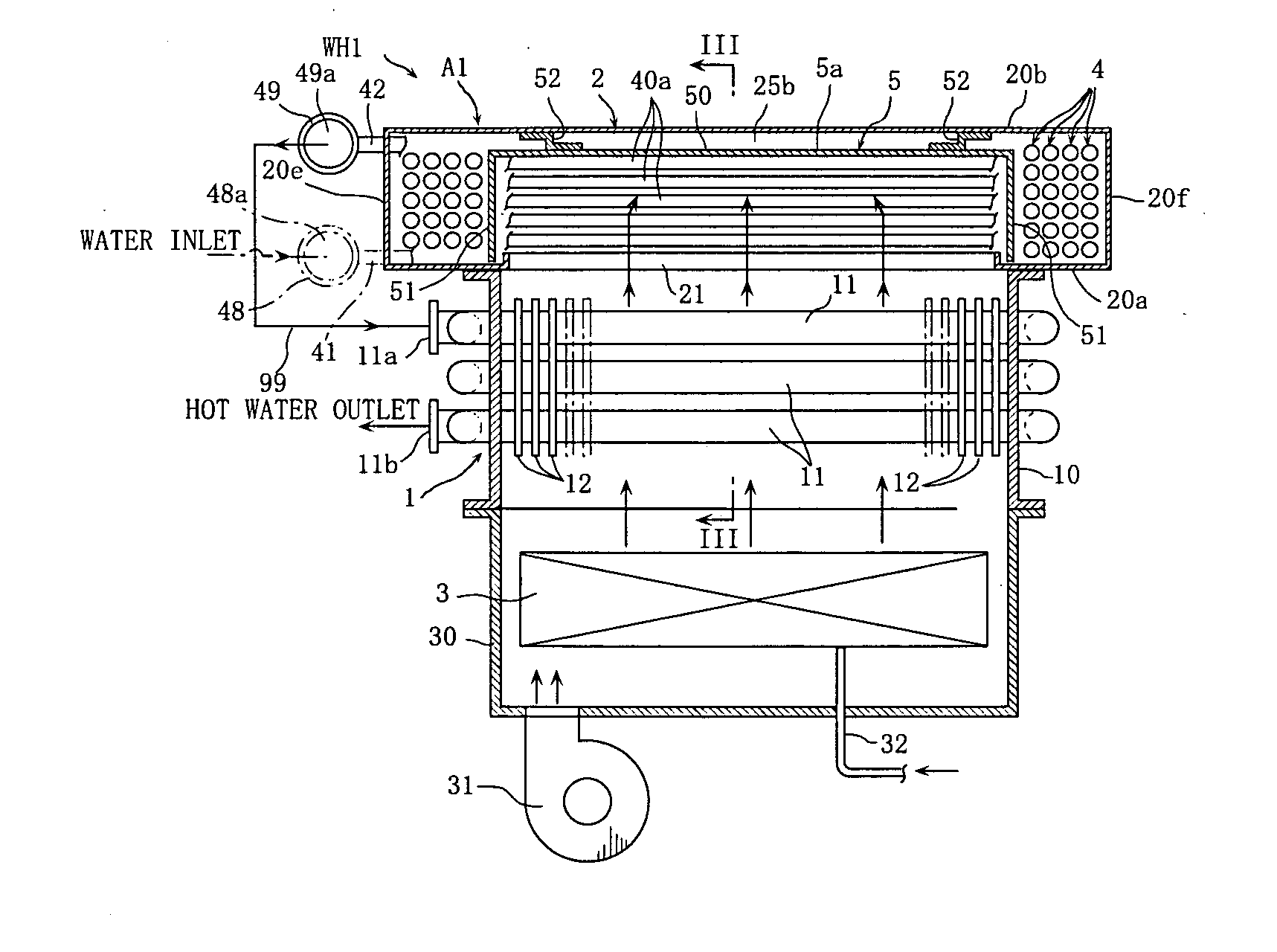
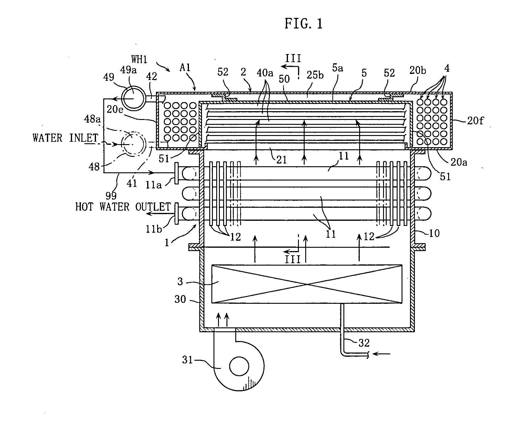
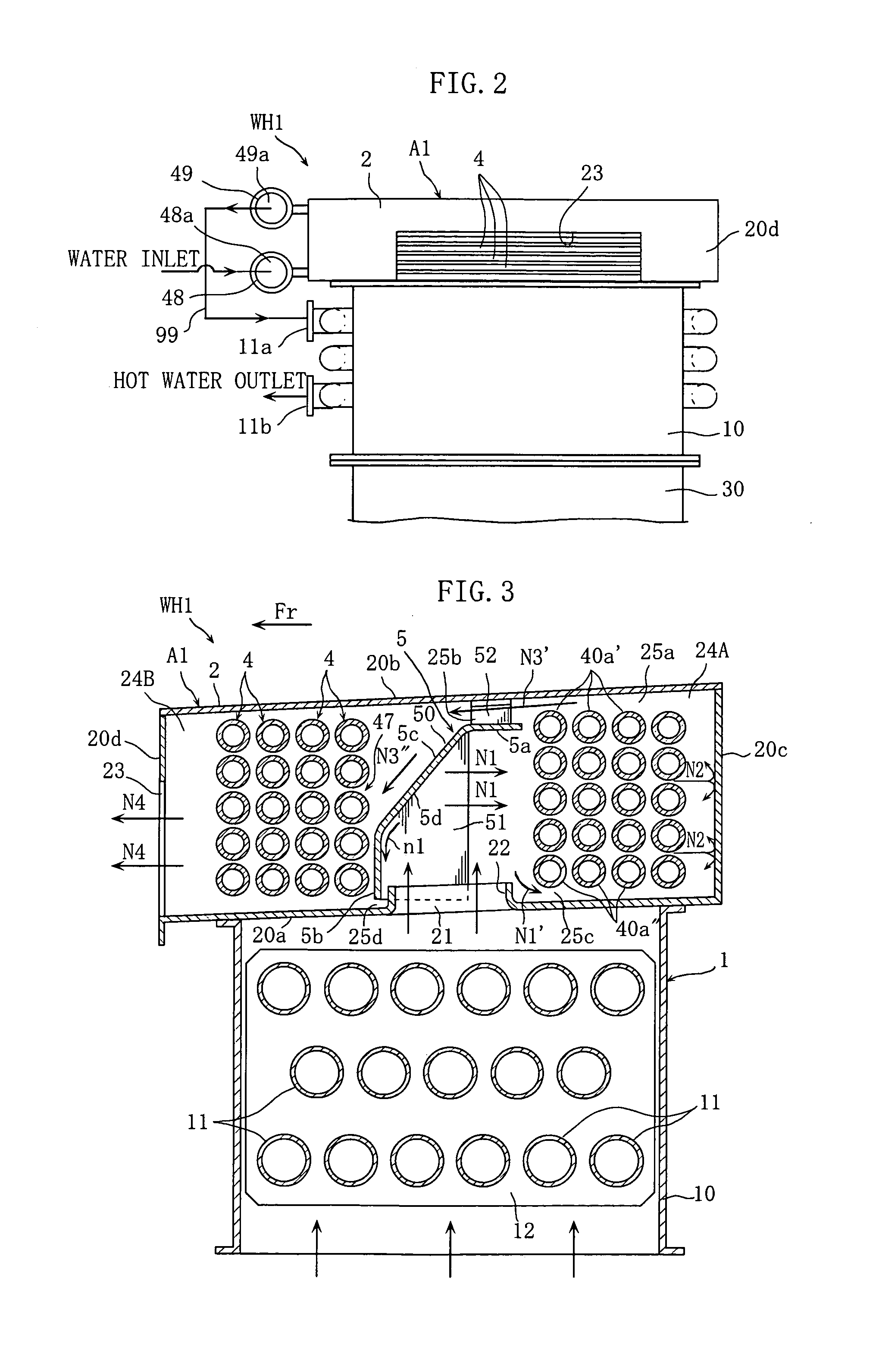
[0045]The water heater WH1 according to the present embodiment is formed as a hot water supplying apparatus. As better shown in FIG. 1, the water heater WH1 includes a combustor 3, a primary heat exchanger 1, and a secondary heat exchanger A1. The secondary heat exchanger A1 is one exemplary heat exchanger according to the present invention. In FIGS. 3 to 5, arrow Fr indicates the forward direction of the secondary heat exchanger A1 and water heater WH1.

[0046]The combustor 3, which is a gas burner for example, is accommodated in a burner case 30 and serves to burn fuel gas supplied from outside through piping 32. A fan 31 feeds air for combustion air upwardly into the burner case 30. The primary heat exchanger 1 serves to recover sensib...


PUM


Abstract

A heat exchanger A1 includes: a case 2 surrounding a heat transfer tube 4; and a guide member 5 for guiding heating gas entering the case 2 through an intake vent 21 to a first space region 24A and then to a second space region 24B, the guide member 5, together with a wall portion 20b, defining therebetween a gap 25b in communication with a gap 25a between the wall portion 20b and the heat transfer tube 4 for allowing part of the heating gas having been guided to the first space region 24A to proceed into the second space region 24B through the gaps 25a and 25b. This arrangement performs efficient heat recovery from the heating gas by effectively utilizing the entire heat transfer tube 4 while alleviating a problem that the case 2 is partially heated to elevated temperatures.

Description

BACKGROUND OF THE INVENTION[0001]1. Field of the Invention[0002]The present invention relates to a heat exchanger configured to perform heat exchange between heating gas, such as combustion gas, and a heat transfer tube, as well as a water heater incorporating the same.[0003]2. Description of the Related Art[0004]One example of a heat exchanger is described in Japanese Patent Laid-Open Publication No. 2008-298325. FIG. 14 illustrates this heat exchanger.[0005]The heat exchanger B illustrated in FIG. 14 includes a case 9, a plurality of heat transfer tubes 8, and a guide member 7 located in a central space defined by the plurality of heat transfer tubes 8. The case 9 has a bottom wall portion 90a and a front wall portion 90b which are formed with an intake vent 91 and an exhaust vent 92 for taking in and exhausting combustion gas. The heat transfer tubes 8 are formed using spiral tubes and accommodated in the case 9. The guide member 7 has an opening 70 oriented in a rearward directi...

Claims


Application Information

Patent Timeline
IPC IPC(8): F24D17/00F28D7/04F24F7/00
CPCF24H1/40F24H1/43F24H8/00F28D7/024F28F9/22Y02B30/102F28D7/0075Y02B30/00
Inventor MATSUNAGA, HIRONAO
Owner NORITZ CORP
Why Eureka
Try Eureka