Tool holding device

a tool and tool technology, applied in the direction of chucks, mechanical apparatus, manufacturing tools, etc., can solve the problems of not always ensuring the reliable supply of coolant to the cutting region, not always ensuring the reliable cooling of the tool, and not always ensuring the clean guidance of the coolant jet along the tool, so as to facilitate the formation of a coolant envelope and improve the quality of the jet forming. , the effect of improving the quality of the j

Inactive Publication Date: 2011-06-30
FRANZ HAIMER MASCHINENBAU KG
View PDF15 Cites 26 Cited by
  • Summary
  • Abstract
  • Description
  • Claims
  • Application Information

AI Technical Summary

Benefits of technology

[0011]The invention improves on a generic tool holding device in that: the coolant conveying device is embodied in the form of at least one flat groove that is situated on an inner surface of the receiving opening and feeds into a region surrounding the tool holding device at a free end of the tool holding body, i.e. at the front end immediately adjacent tool to tool shank; and / or the region of the free end of the tool holding body is provided with a coolant reservoir and / or coolant collecting chamber into which at least one coolant conveying device feeds; the coolant reservoir and / or coolant collecting chamber is connected via an annular gap to the region surrounding the tool holding device; and the annular gap and coolant reservoir and / or coolant collecting chamber are at least partially delimited by the tool shank. It is thus possible to form a closed or essentially closed coolant envelope, which completely or almost completely encloses the tool shank or tool at the outlet, i.e. in the region of the front end of the tool holder. The provision of flat grooves as defined by the invention, which are at least wider than they are deep, forms a particularly thin-filmed, fanned-out coolant jet; it has been observed that fanned-out, thinner coolant jets have a greater tendency to at least partially unite into a closed coolant envelope against the tool shank or tool, outside the tool holder. Observations have also demonstrated that an embodiment of the coolant jet that is relatively thin in the radial direction reduces the tendency of the coolant to separate from the rotating tool, thus reducing the mushrooming of the coolant envelope. Particularly at high rotating speeds and the resulting high centrifugal forces, this helps to produce a thin, closed coolant envelope.
[0014]It is particularly preferable to provide the flat grooves with a groove bottom having a cylindrical segment surface that is curved concentric to an axial longitudinal central axis of the tool holding device. This forms ring segment-like exit gaps at the free end of the tool holding body, which are particularly able to converge a preshaping of coolant jets to the diameter of the tool. It turns out to be advantageous to distribute the flat grooves unevenly around the circumference in the circumference direction of the receiving bore. This reduces the excitation of vibrations in the clamped tool. The excitation of vibrations occurs due to the alternation of regions of different rigidity (clamping surface—groove). With an asymmetrical distribution of grooves or with different widths of the grooves, the inevitable excitation of vibrations occurs in an irregular fashion.
[0016]It has also turned out to be advantageous for the depth t of the flat grooves to be approximately 0.5% to 15%, in particular 1% to 10% of the tool diameter D. This makes it possible to strike a good compromise between the required coolant quantity and the thinness of the emerging coolant jet desired according to the invention.
[0018]A particularly favorable jet formation can be achieved if the flat grooves, at least in the end region, are embodied so that their width b expands, in particular conically, in the direction toward the free end of the tool holding device along the axial longitudinal central axis. This measure contributes to ensuring a secure hold of the tool in the tool holding opening and to fulfilling the desired requirements with respect to the jet quality of the emerging coolant. In particular, this facilitates the formation of a coolant envelope that is closed in the circumference direction.
[0019]Another variant of the groove-routing of the flat grooves inside the receiving opening is to embody them as coiled helical fashion; in particular, a helical coiling oriented in the opposite direction from the tool's working rotation direction has the advantage that the emerging cooling fluid is given a tangential velocity component oriented in opposition to the tangential velocity of the tool in the circumference direction. It is consequently possible to achieve an improved jet forming quality.

Problems solved by technology

In a shrink fit chuck of this kind, it has been observed that particularly at high rotation speeds that occur during operation of the chuck and particularly with small tool diameters, the jet of coolant emerging from the end separates from the tool and a reliable supply of coolant to the cutting region is not always guaranteed, particularly with longer tools.
This, too, does not always guarantee a reliable cooling of the tool in the cutting region / material-removing region.
The exit of the coolant into the open air here occurs in a relatively indefinite fashion and cannot always guarantee a clean guidance of the coolant jet along the tool.
This is not desirable.

Method used


Image

  • Tool holding device
  • Tool holding device
  • Tool holding device

Examples


Embodiment Construction

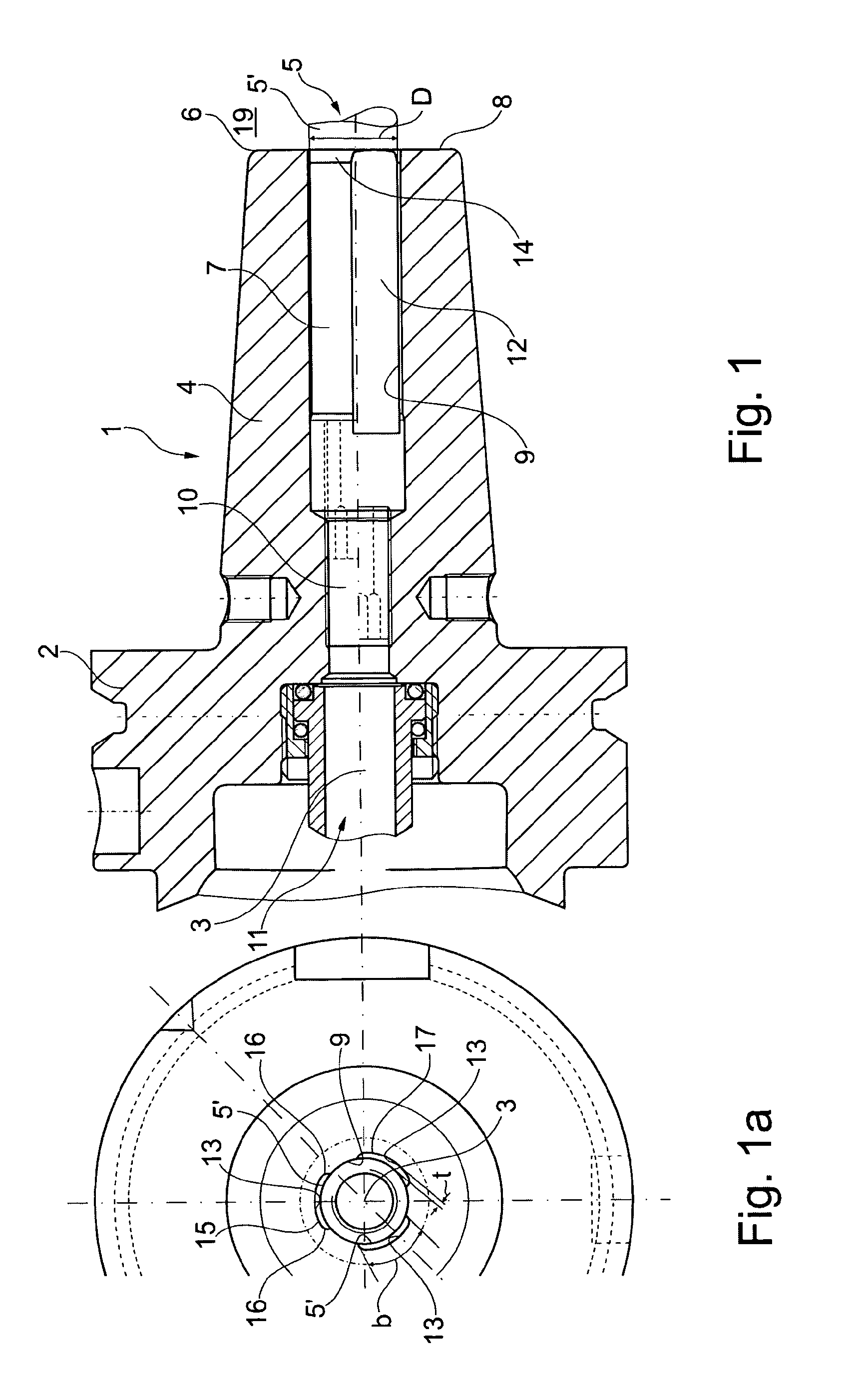
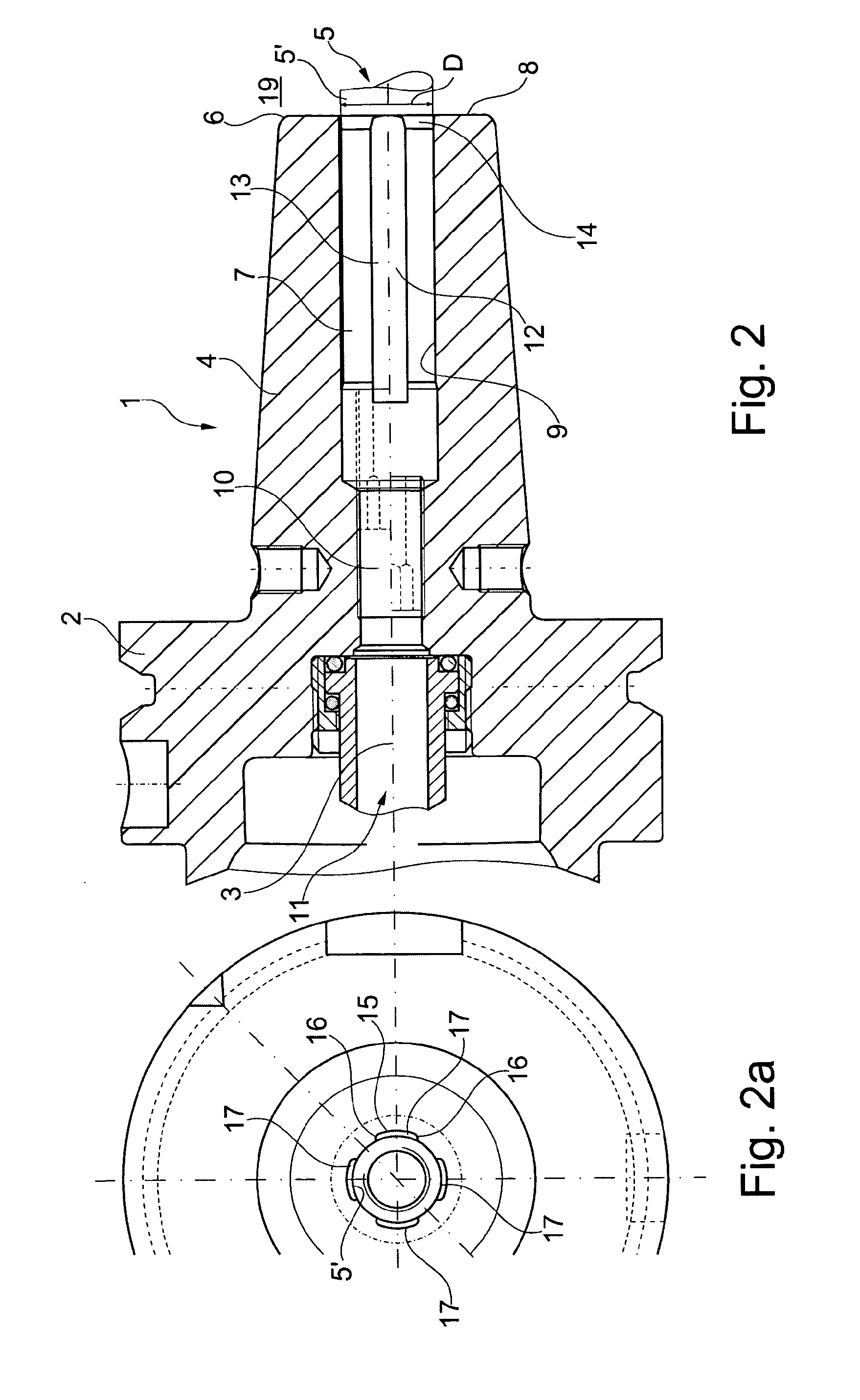
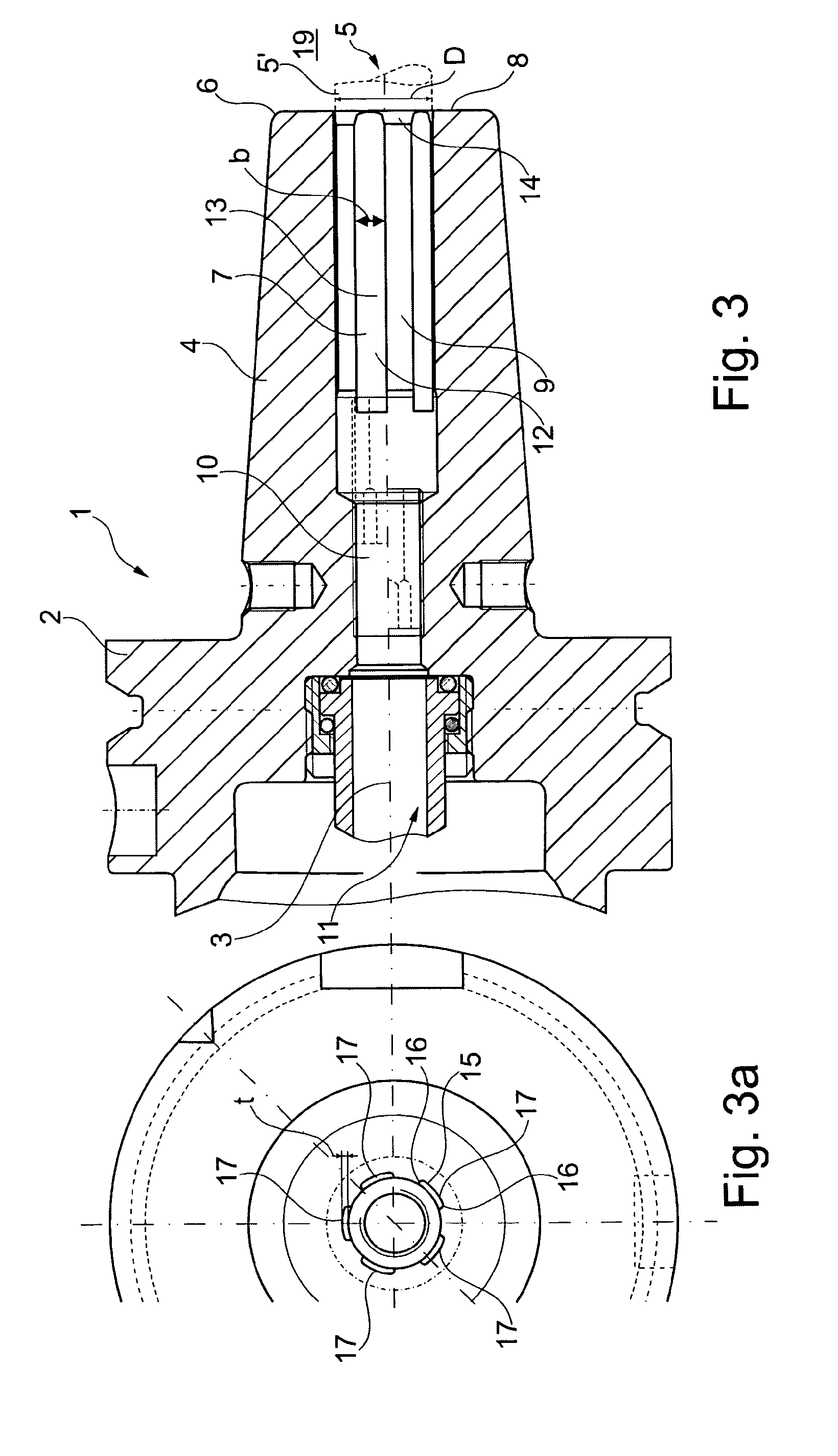
[0063]The invention is disclosed below in conjunction with various exemplary embodiments of tool holding devices embodied in the form of a shrink fit chuck. Naturally, a person of average skill in the art can easily transfer the details disclosed to tool holding devices embodied in the form of Weldon chucks or whistle-notch chucks. The same is true for tool holding devices embodied in the form of collet chucks such as ER collet chucks, OZ collet chucks, and / or high-precision collet chucks.

[0064]A first embodiment of a tool holding device 1 according to the invention (FIGS. 1 and 1a) has a tool holding body 2 with an axial longitudinal central axis 3 around which the tool holding body 2 is embodied as essentially rotationally symmetrical. The tool holding body 2 has a clamping section 4 for accommodating a tool / rotating tool 5. The tool 5 has a tool shank 5′ and this shank 5′ can be inserted into the receiving opening 7 from the free end 6 of the tool holding body 2. The tool shank 5...


PUM


Abstract

The invention relates to a tool holding device comprising a tool holding body for securing, in a fixed manner, a rotary tool comprising a shaft, provided with a clamping section and a receiving opening for the shaft of the tool, a coolant feeding device for pressurized fluid, at least one coolant guiding device for guiding the coolant into a clamped tool shaft. The coolant guiding device is designed as at least one flat groove on an inner side of the receiving opening, joining to the front side on a free end of the tool holding body and directly adjacent to the tool shaft in the surroundings of the tool holding device or a coolant storing chamber and / or collecting chamber is provided in the region of the free end of the tool holding body, to which the at least one coolant guiding device joins. The coolant storing chamber and / or collecting chamber is connected by means of an annular gap to the surroundings of the tool holder device. The coolant storing chamber and / or collecting chamber and the annular gap are defined at least partially by the work shaft.

Description

FIELD OF THE INVENTION[0001]The invention relates to a tool holding device. In particular, the invention relates to a tool holding device for tools with a shank, e.g. a shrink fit chuck, or embodied in the form of a flat chuck such as a Weldon chuck or whistle-notch chuck, as well as in the form of a collet chuck such as an ER collet chuck, an OZ collet chuck, or a high-precision collet chuck.BACKGROUND OF THE INVENTION[0002]EP 1 074 322 A1 has disclosed a rotating chuck that is embodied in the form of a shrink fit chuck for a tool, in particular for a drill bit or milling bit. This rotating chuck has a coolant supply conduit. The shrink fit chuck has a receiving bore for the tool in which the tool is secured by means of a shrink fit seat during operation. The receiving bore has a number of axially extending longitudinal grooves distributed around its inner circumference, which are connected to the supply conduit for a coolant. The grooves extend to the free end of the shrink fit ch...

Claims


Application Information

Patent Timeline
Patent Type & Authority Applications(United States)
IPC IPC(8): B23B31/02
CPCB23B31/02Y10T279/17111B23B2250/12B23B31/1179
Inventor HAIMER, FRANZ
Owner FRANZ HAIMER MASCHINENBAU KG
Why Eureka
Try Eureka