Machining tool

A technology of cutting tools and cutting tools, which is applied in the field of cutting tools, can solve problems such as poor and smooth operation, and achieve the effect of reducing vibration excitation and improving smooth operation

Inactive Publication Date: 2018-07-17
ALBERT KNEBEL HLDG
View PDF8 Cites 0 Cited by
  • Summary
  • Abstract
  • Description
  • Claims
  • Application Information

AI Technical Summary

Problems solved by technology

Measures to improve cut quality lead to worse smooth operation as a side effect

Method used


Image

  • Machining tool
  • Machining tool
  • Machining tool

Examples


Embodiment Construction

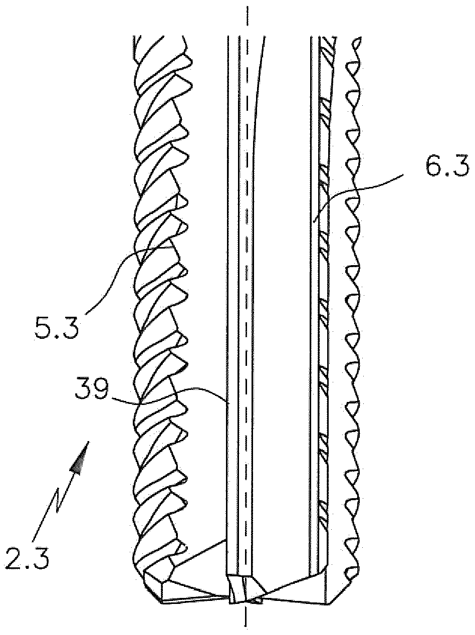
[0029] figure 1 The cutting edge section 1.1 of the cutting tool 2 is shown. A further section 1.2 is attached to the cutting edge section 1.1 from above, with which the cutting tool 2 can be clamped.

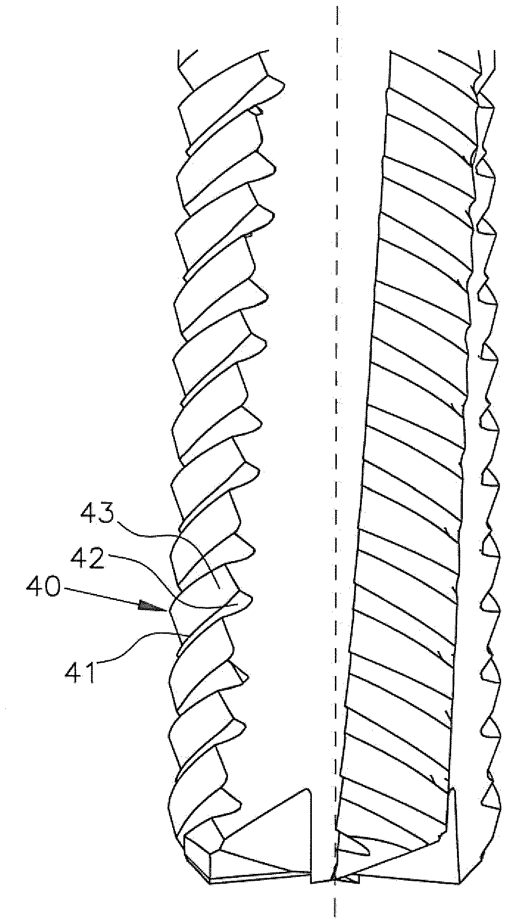
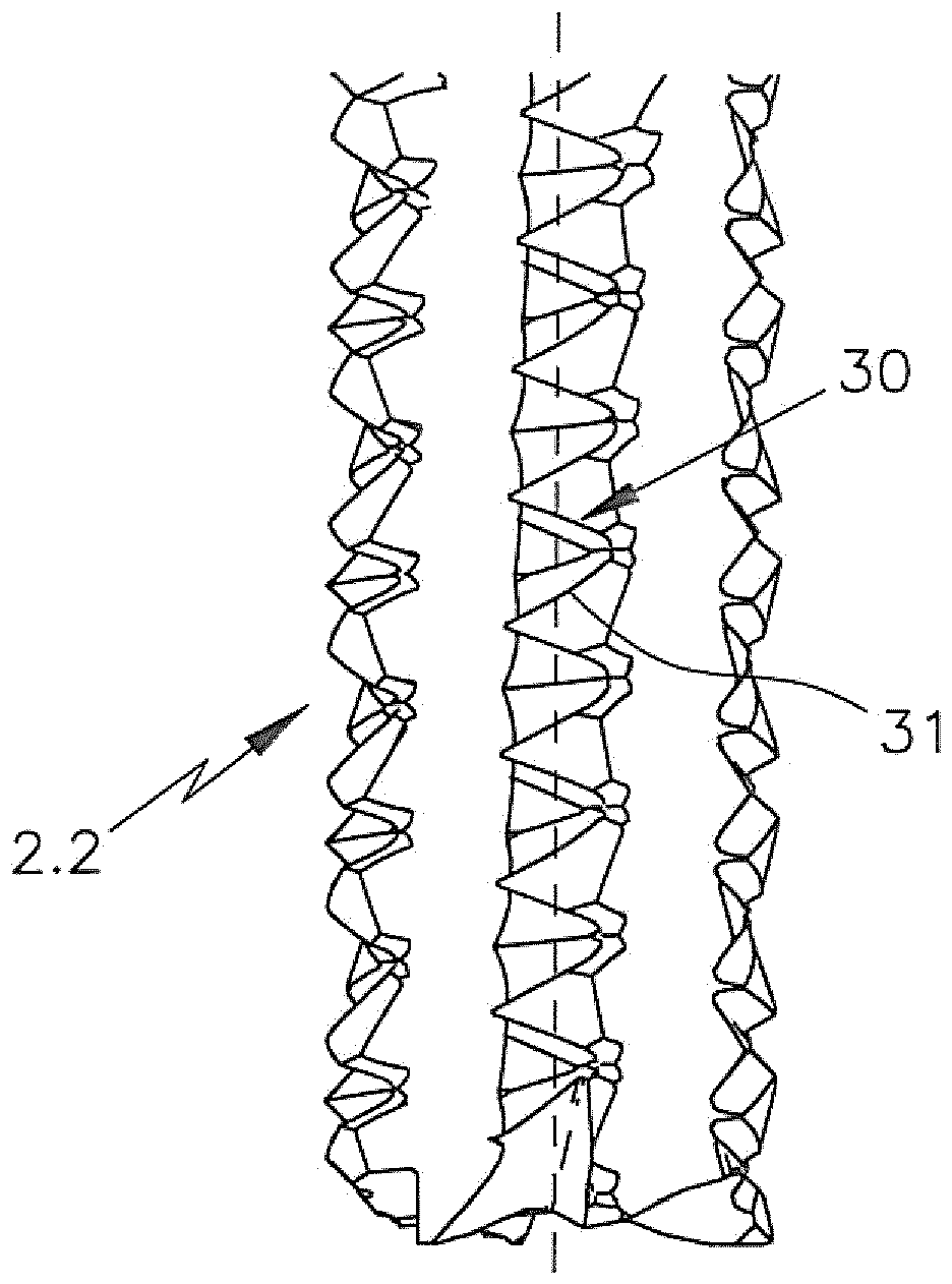
[0030] The cutting tool 2 is designed approximately cylindrically. It has cutting grooves 3, 4 which space the edges 5, 6, 7 from each other. According to the edger 5 , the edger 5 to 7 has a cutting edge 10 on the peripheral side. The cutting edges 10 are spaced apart from each other by grooves 11 .

[0031] figure 2 The unwinding of the cutting edge, for example the cutting edges 13 , 14 of the cutting edge 10 , is shown. The cutting edges 14 have positive helix angles a1, a2, an. This means that the angles a1 , a2 , an are positive relative to the longitudinal axis 2 of the cutting tool 2 . All cutting edges with their associated cutting edges 14 have different helix angles a1 , a2 , an. This means, a1≠a2≠an.

[0032] The cutting edge with the cutting edge 13 corre...


PUM


Abstract

A machining tool (2, 2.2, 2.3) for machining fiber-reinforced materials has a plurality of machining flutes (3, 4) which are separated from each other in the circumferential direction by lands (5, 6,7, 20, 5.3, 6.3); at least one land (5, 6, 7, 20, 5.3, 6.3) has a plurality of cutting edges (10, 21, 30, 31, 39) on its circumferential side, the cutting edges extending at a helix angle (a1-an, b1-bn, c1-cn, d1-dn) > 25 degrees relative to the longitudinal axis (15) of the machining tool (2, 2.2, 2.3). The disclosed machining tool (2, 2.2, 2.3) is characterized in that at least two cutting edges(10, 21, 30, 31, 39) on the at least one land (5, 6, 7, 20, 5.3, 6.3) have different helix angles (a1-an, b1-bn, c1-cn, d1-dn).

Description

technical field [0001] The invention relates to a cutting tool for machining fiber-reinforced production materials, with a plurality of cutting grooves, which make the edges spaced apart from each other in the peripheral direction, wherein at least one edge has a plurality of cutting edges on its peripheral side , which has a helix angle of >25° in absolute value relative to the longitudinal axis of the cutting tool. Background technique [0002] A cutting tool of this type is known, for example, from document WO 2014 / 056582 A1. The cutting tool described here has a plurality of cutting grooves which space the flight flights which lie around the cylindrical core section from one another in the circumferential direction. In this case, at least one of the flight flights is designed as a pre-processing flight and at least one other of the flight flights is designed as a post-processing flight, each of which has a helical segment-shaped winding around the cutting tool along ...

Claims


Application Information

Patent Timeline
Patent Type & Authority Applications(China)
IPC IPC(8): B23C5/10
CPCB23C5/10B23C2210/0492B23C2226/27
Inventor P.维尔曼G.赫尔布舍
Owner ALBERT KNEBEL HLDG
Why Eureka
Try Eureka