
Radio communication system, radio base station, radio relay station and radio communication method

a radio communication system and radio relay technology, applied in radio transmission, electrical equipment, network topologies, etc., can solve the problems of increasing the processing load of radio base stations, increasing communication resource consumption, and increasing the processing load of performing cell searches

Active Publication Date: 2011-06-30
KYOCERA CORP
View PDF4 Cites 17 Cited by
  • Summary
  • Abstract
  • Description
  • Claims
  • Application Information

AI Technical Summary

Benefits of technology

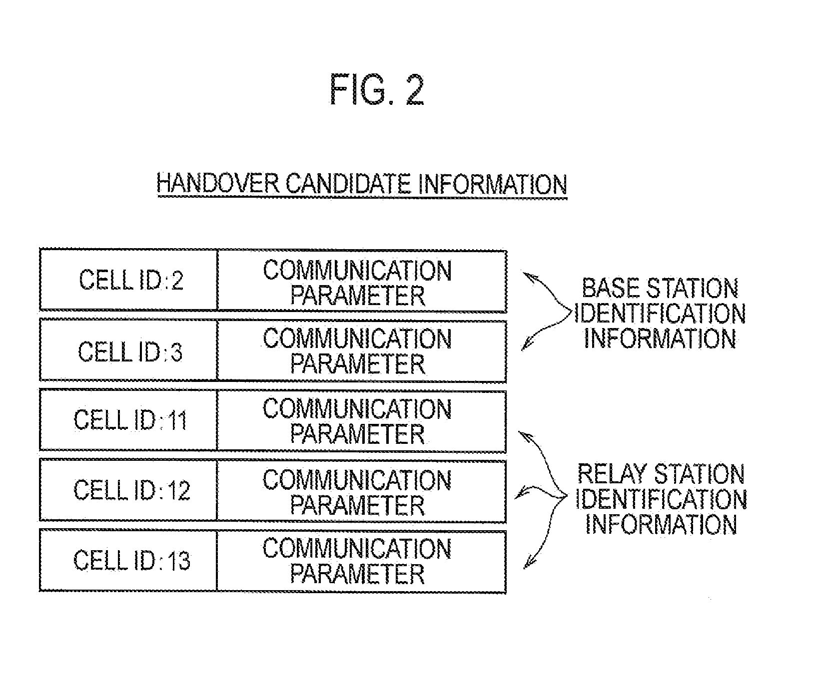
The present invention provides a solution for a radio communication system to allow a radio terminal to connect to a radio relay station even if the relay station changes frequently. This is achieved by notifying the radio terminal of the handover candidate information including a predetermined number of pieces of relay station identification information, which allows the radio terminal to detect and connect with the relay station. This reduces the processing load and communication resource consumption for the radio base station.

Problems solved by technology

For this reason, if the radio base station updates relay station identification information to be included in handover candidate information according to this change, there is a problem that the processing load of the radio base station increases.
However, such a method requires tens of thousands to hundreds of thousands of pieces of relay station identification information to be included in the handover candidate information, which increases communication resource consumption as well as the processing load for performing a cell search.

Method used


Image

  • Radio communication system, radio base station, radio relay station and radio communication method
  • Radio communication system, radio base station, radio relay station and radio communication method
  • Radio communication system, radio base station, radio relay station and radio communication method

Examples


Embodiment Construction

[0020]Next, a description will be given with reference to the drawings of a radio communication system according to an embodiment of the present invention. To be specific, descriptions will be given of (1) Schematic Configuration of Radio Communication System, (2) Example of Handover Candidate Information, (3) Detailed Configuration of Radio Communication System, (4) Operation of Radio Communication System, (5) Conclusion, and (6) Other Embodiments. The same or similar components are assigned the same or similar reference numerals in the descriptions of drawings in the following embodiments.

(1) SCHEMATIC CONFIGURATION OF RADIO COMMUNICATION SYSTEM

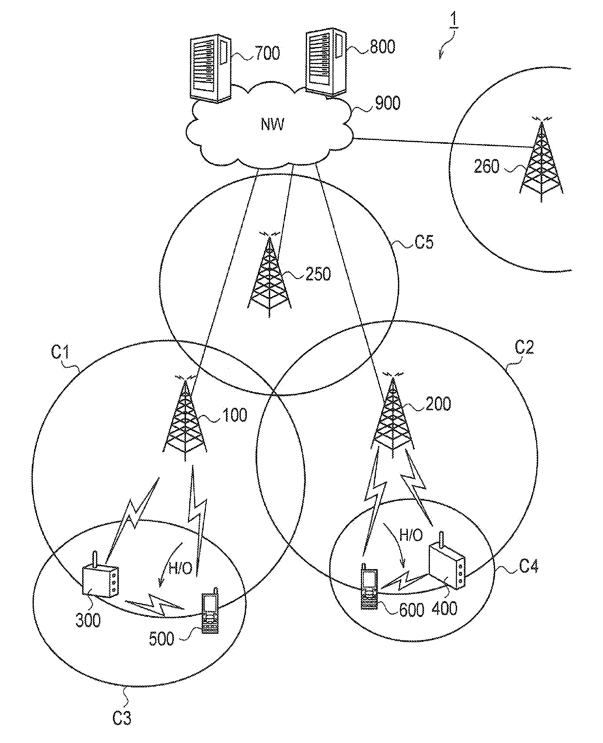
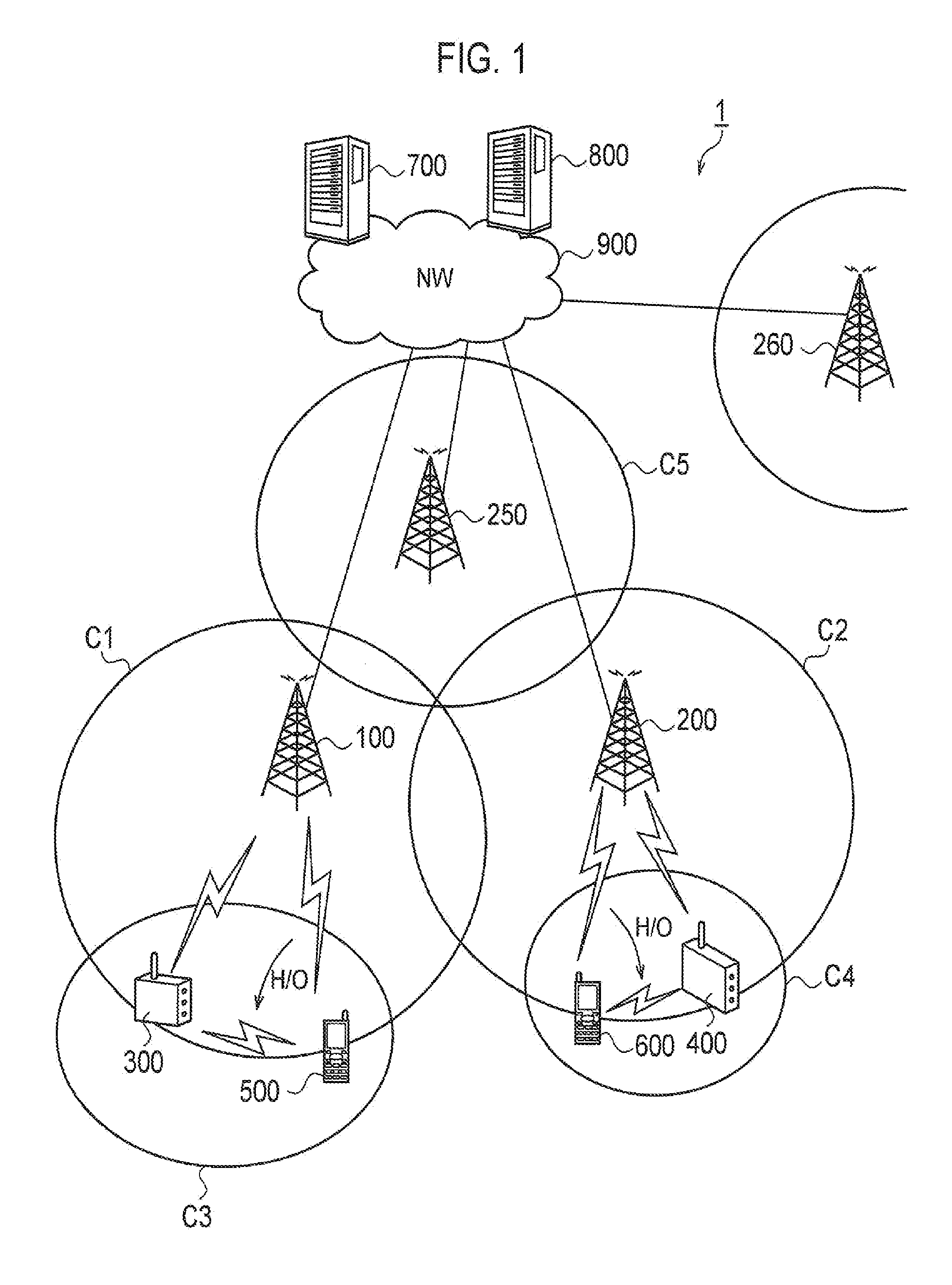
[0021]FIG. 1 is a schematic configuration diagram of a radio communication system 1 according to the embodiment.

[0022]As shown in FIG. 1, the radio communication system 1 includes a radio base station 100 and a radio terminal 500 connected to the radio base station 100. The radio base station 100 forms a cell C1 which is an area connectable...


PUM


Abstract

The radio communication system has a radio base station, a radio relay station connectable to the radio base station, and a radio terminal configured to connect to the radio base station. The radio base station notifies the radio terminal of identification information for a predetermined number of relay stations based on the number of radio relay stations that can be simultaneously connected to the radio base station. When the radio relay station is connected to the radio base station, identification information for any one of the relay stations is assigned to the radio relay station. The radio terminal performs a cell search based on the relay station identification information.

Description

TECHNICAL FIELD[0001]The present invention relates to a radio communication system, a radio base station, a radio relay station and a radio communication method for notifying a radio terminal of handover candidate information indicating handover candidates of the radio terminal.BACKGROUND ART[0002]In a radio communication system, a radio terminal performs handover to switch its connection destination to a radio base station having better conditions. To enable execution of handover, the radio base station notifies the radio terminal connected to the radio base station itself of handover candidate information including base station identification information for identifying radio base stations in a neighborhood of the radio base station itself (referred to below as “neighboring radio base station”) (see Patent Document 1). Such handover candidate information is also referred to as a neighbor list.[0003]The radio terminal performs a search (so-called cell search) on the neighboring rad...

Claims


Application Information

Patent Timeline
Patent Type & Authority Applications(United States)
IPC IPC(8): H04W36/00
CPCH04B7/155H04W84/047H04W36/0061H04B7/2606H04B7/14H04W36/08H04W48/16H04W88/08
Inventor NINAGAWA, TAKAYASU
Owner KYOCERA CORP
Learn More