Irrigated Catheter Employing Multi-Lumenal Irrigation Tubing

a multi-lumenal, catheter technology, applied in the field of catheters, can solve the problems of not being able to provide certain areas of catheters not irrigated, and saline bags, etc., to achieve the effect of delivering accurate, consistent and predictable irrigation flows, and not being able to use multiple such pumps to provide multiple irrigation flows

Active Publication Date: 2011-06-30
ST JUDE MEDICAL ATRIAL FIBRILLATION DIV
View PDF12 Cites 27 Cited by
  • Summary
  • Abstract
  • Description
  • Claims
  • Application Information

AI Technical Summary

Benefits of technology

[0020]Still another advantage of the present invention is that the multiple dedicated and / or independent irrigation flows may be driven by a single pump.

Problems solved by technology

For example, in an irrigated catheter that includes a pressure-driven irrigation flow, if an irrigation passageway becomes obstructed, the irrigation fluid will seek lower pressure outlets and redistribute to other irrigation passageways, leading to a situation where certain areas of the catheter are not irrigated to the extent desired.
Saline bags, however, are not ideal for delivering accurate, consistent, and predictable irrigation flows.
To overcome these disadvantages associated with saline bags, an irrigation or infusion pump may be employed, but it is not economical to utilize multiple such pumps to provide multiple irrigation flows.

Method used


Image

  • Irrigated Catheter Employing Multi-Lumenal Irrigation Tubing
  • Irrigated Catheter Employing Multi-Lumenal Irrigation Tubing
  • Irrigated Catheter Employing Multi-Lumenal Irrigation Tubing

Examples


first embodiment

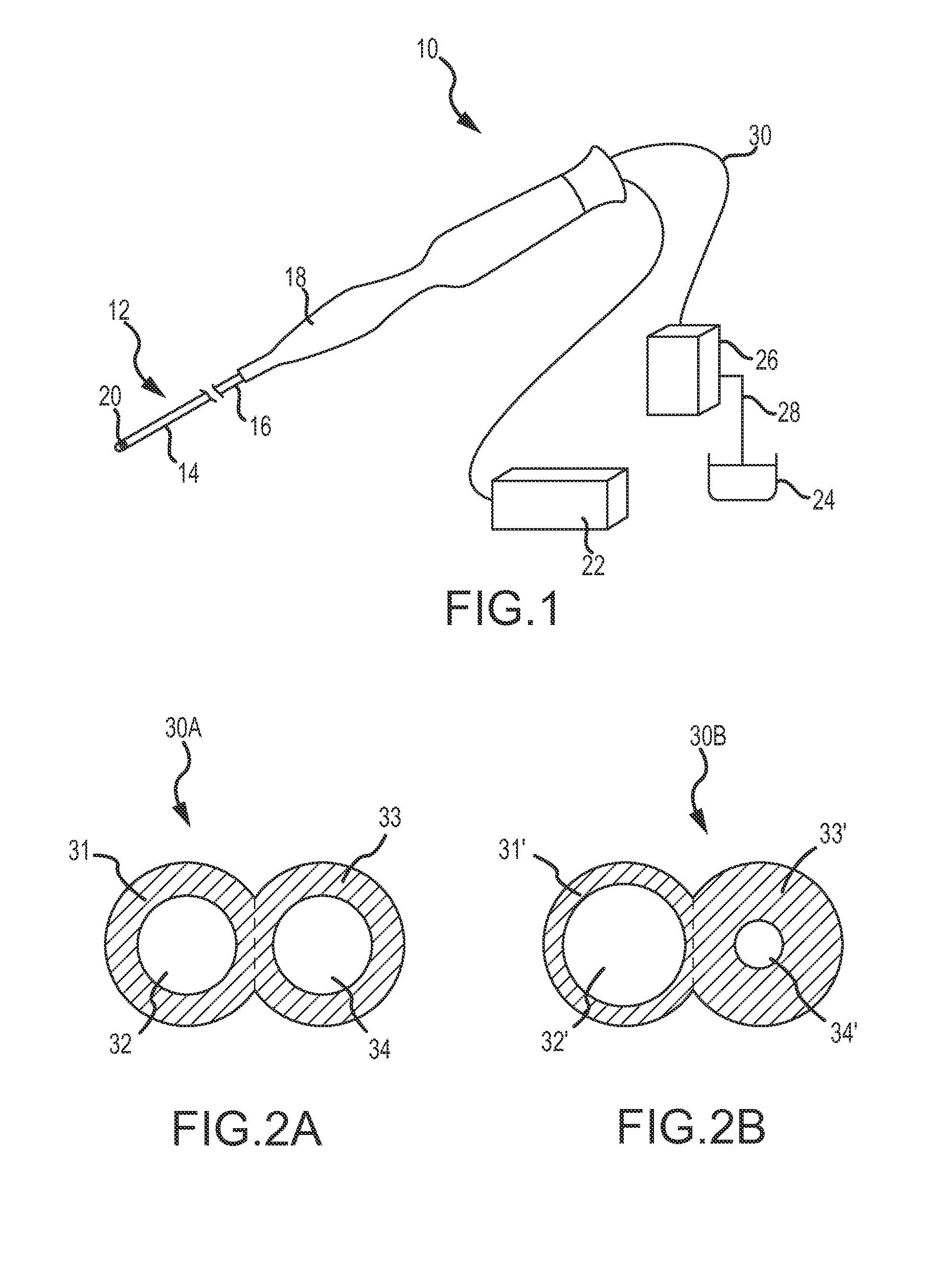
[0041]FIG. 2A depicts an axial cross-section of multi-lumenal tubing 30 denoted 30A. Specifically, FIG. 2A depicts an embodiment where the multi-lumenal tubing includes two conjoined fluid delivery tubes 31 and 33, with a hypothetical boundary between fluid delivery tubes 31 and 33 shown in dashed line. Fluid delivery tubes 31 and 33 respectively define two fluid delivery lumens (also referred to herein as “irrigation lumens”): first fluid delivery lumen 32 and second fluid delivery lumen 34. In the embodiment shown in FIG. 2A, first fluid delivery lumen 32 and second fluid delivery lumen 34 have substantially identical axial cross-sectional areas. That is, first fluid delivery lumen 32 and second fluid delivery lumen 34 are substantially congruent, having the same size (e.g., the same diameter) and the same shape (e.g., substantially circular).

second embodiment

[0042]FIG. 2B depicts an axial cross-section of multi-lumenal tubing 30 denoted 30B. Specifically, FIG. 2B depicts an embodiment where the multi-lumenal tubing includes two conjoined fluid delivery tubes 31′ and 33′, respectively defining a first fluid delivery lumen 32′ and a second fluid delivery lumen 34′. As with FIG. 2A, a hypothetical boundary between delivery tubes 31′ and 33′ is shown in dashed line. In contrast to the embodiment of FIG. 2A, however, fluid delivery lumens 32′ and 34′ have different axial cross-sectional areas (e.g., they are different sizes).

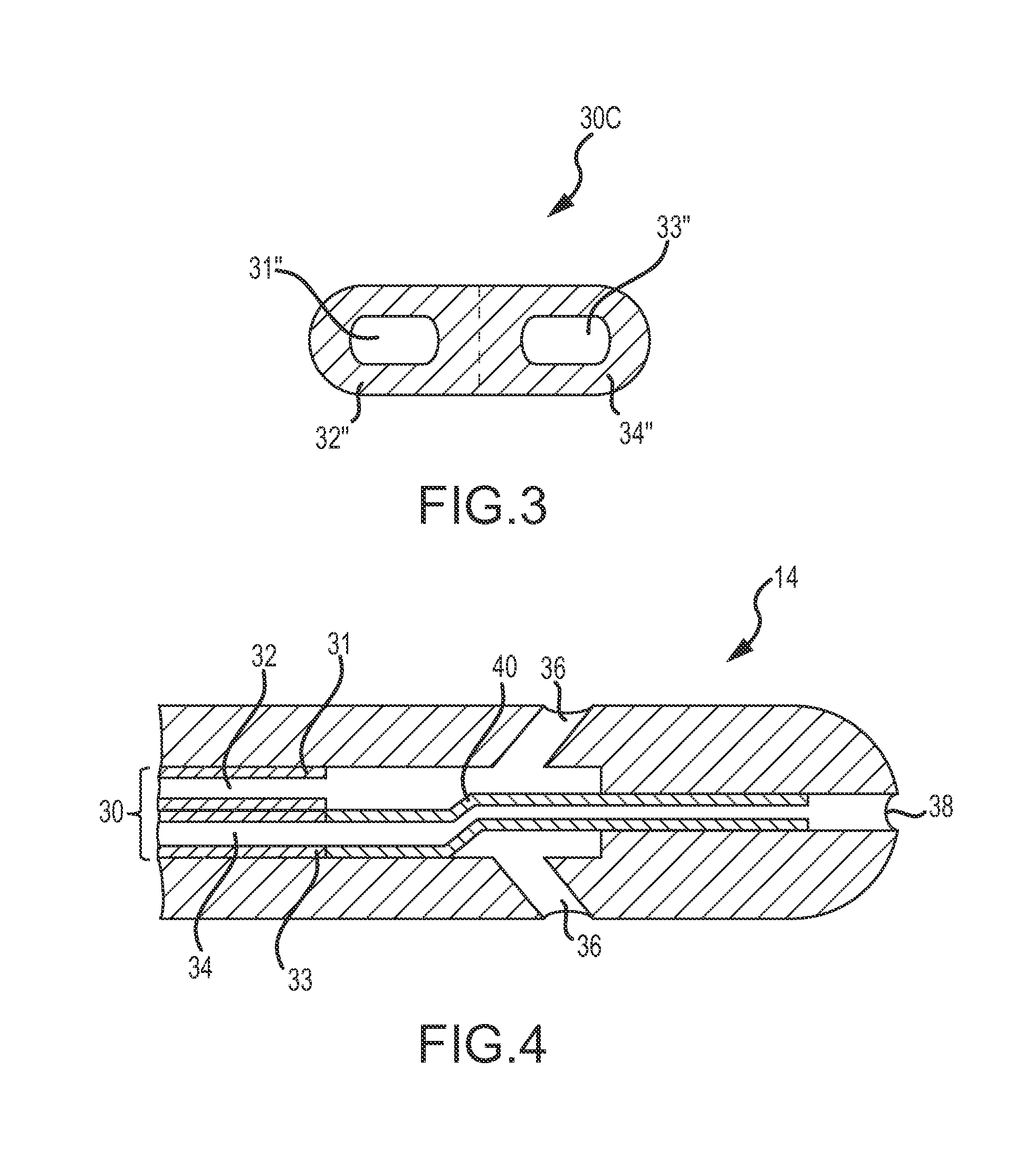
[0043]FIGS. 2A and 2B depict multi-lumenal tubing 30 that has, overall, an axial cross-sectional shape resembling a “figure eight” due to the joining of two substantially circular tubing members. Alternatively, as shown in FIG. 3, multi-lumenal tubing 30, denoted as 30C, may have an oval (or otherwise flattened) axial cross-sectional shape. Of course, as also shown in FIG. 3, the fluid delivery lumens 32″ and 34″, define...


PUM

PropertyMeasurementUnit
axial cross-sectional shapesaaaaaaaaaa
shapeaaaaaaaaaa
energyaaaaaaaaaa

Abstract

An irrigated catheter includes a catheter body having both proximal and distal irrigation passageways. A first fluid delivery tube feeds the proximal irrigation passageway and is fluidly isolated from the distal irrigation passageway, while a second fluid delivery tube feeds the distal irrigation passageway and is fluidly isolated from the proximal irrigation passageway. Typically, the first and second fluid delivery tubes will be unitary, at least through the catheter body. The overall shape of the first and second fluid delivery tubes, as well as their respective lumens, may vary as necessary for a particular application of the irrigated catheter. The system also includes an irrigation fluid source and at least one pump to deliver the irrigation fluid through the irrigation passageways. Typically, the pump will be a volume-driven pump, such as a rolling pump.

Description

BACKGROUND OF THE INVENTION[0001]a. Field of the Invention[0002]The instant invention relates to catheters that are used in the human body. In particular, the instant invention relates to an irrigated catheter utilizing multi-lumenal irrigation tubing to provide multiple dedicated and / or independent irrigation flows. The present invention also relates to methods of manufacturing and using such a catheter.[0003]b. Background Art[0004]Catheters are used for an ever-growing number of procedures. For example, catheters are used for diagnostic, therapeutic, and ablative procedures, to name just a few examples. Typically, the catheter is manipulated through the patient's vasculature and to the intended site, for example a site within the patient's heart.[0005]A typical electrophysiology catheter includes an elongate shaft and one or more electrodes on the distal end of the shaft. The electrodes may be used for ablation, diagnosis, or the like. Electrophysiology catheters also often includ...

Claims


Application Information

Patent Timeline
Patent Type & Authority Applications(United States)
IPC IPC(8): A61M25/00A61M1/00A61B18/18B23P17/04
CPCA61B18/1492A61B2018/00214A61B2218/002A61M25/0009Y10T29/49826A61M25/007A61M25/0071A61M2025/0037A61M25/003
Inventor WANG, HUISUNJUST, DALE E.PURYEAR, HARRY A.
Owner ST JUDE MEDICAL ATRIAL FIBRILLATION DIV
Why Eureka
Try Eureka