Cutting or Scoring Balloon, System and Method of Making a Cutting or Scoring Balloon

Active Publication Date: 2011-06-30
COOK MEDICAL TECH LLC
View PDF10 Cites 49 Cited by
  • Summary
  • Abstract
  • Description
  • Claims
  • Application Information

AI Technical Summary

Benefits of technology

[0013]The provision of a thicker part to the balloon wall at the region of the or each scoring element causes the thicker part of the balloon wall to stretch differentially compared to the remainder and thinner of the balloon wall and thus reduces or avoids any stretching and thus flattening of the scoring element or elements. This can also avoid the need to have scoring elements which are otherwise unnecessarily thickened to withstand manufacturing and usage stretching and thus can lead to a balloon catheter with a smaller collapsed profile than prior art devices.
[0025]For this purpose, the or each scoring element support may be in the form of a slidable guide having a channel or recess therein able to support the apex of the or each scoring element and biased towards the raw material form by, for example, a sprung element. Such scoring element supports provide a support to the apex or point of the scoring elements as the raw material form is inflated to produce the final balloon, assisting in ensuring that these do not become blunt during the formation process.

Problems solved by technology

However, coronary bypass surgery is a very invasive procedure that is risky and requires a long recovery time for the patient.
One problem that may be encountered with conventional angioplasty techniques is the proper dilation of stenosed regions that are hardened and / or have become calcified.
Hardened regions of stenosis can be difficult to completely dilate using conventional balloons because hardened regions tend to resist the expansion pressures applied by conventional balloon catheters.
There are problems, however, with such cutting balloons, particularly related to their manufacture.
This is a laborious process which furthermore results in a cutting balloon with limited compressibility, making it unsuitable for some medical applications.

Method used


Image

  • Cutting or Scoring Balloon, System and Method of Making a Cutting or Scoring Balloon
  • Cutting or Scoring Balloon, System and Method of Making a Cutting or Scoring Balloon
  • Cutting or Scoring Balloon, System and Method of Making a Cutting or Scoring Balloon

Examples


Embodiment Construction

[0038]It is to be understood that the drawings do not show the components to scale. In many instances dimensions are exaggerated in the drawings in order to show more clearly one or more features of the preferred embodiments.

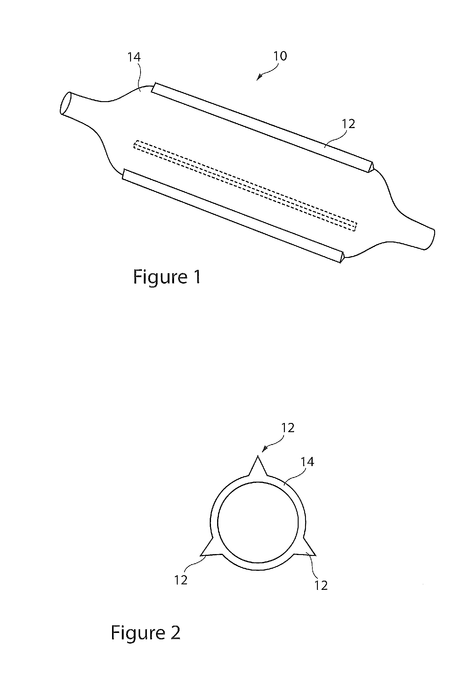
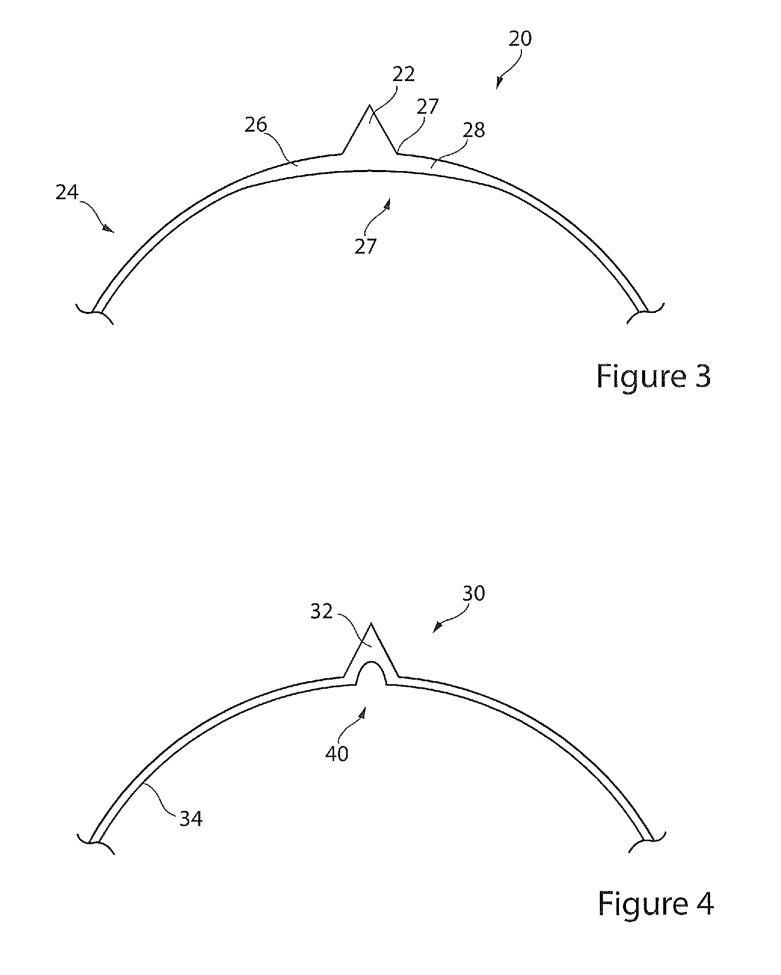
[0039]Referring first to FIG. 1, there is shown a perspective view in schematic form of an embodiment of cutting or scoring balloon 10 of elongate shape and provided at its periphery with a plurality of scoring or cutting elements 12 extending longitudinally along the balloon. The scoring elements 12 are formed integrally with the balloon wall 14 and in the preferred embodiment are of the same material.

[0040]There are preferably provided a plurality of such scoring elements 12, advantageously spaced substantially evenly around the circumference of the balloon 10. In the embodiments which follow there are provided three scoring elements 12, although the number of these will be dependent upon the particular application and wishes of the user / designer.

[0041]FIG. 1 ...


PUM

PropertyMeasurementUnit
Lengthaaaaaaaaaa
Thicknessaaaaaaaaaa
Pressureaaaaaaaaaa

Abstract

A cutting or scoring balloon (10) of elongate shape and provided at its periphery with a plurality of scoring elements (12) extending longitudinally along the balloon. The scoring elements (12) are formed integrally with the balloon wall (14) and in the preferred embodiment are of the same material. A raw material form (20) for producing the balloon (10) is provided with a series of zones (26, 28) of greater thickness compared to the remainder of the balloon wall (24). These zones (26, 28) are located adjacent respective ribs (22) and extend longitudinally along the balloon wall for substantially the same distance as the ribs (22). The zones (26, 28) ensure that these will expand (stretch) preferentially compared to the remainder of the raw material form (20) and in particular the ribs (22), with the effect that the ribs (22) will not tend to be stretched. Apparatus for forming a balloon (10), includes a chamber (50) for holding the raw material form (20, 30) on fittings (52). A pumping and control unit (56) is provided for feeding pressurized air to the interior of the chamber. Within the casing (50) there is provided a series of scoring element supports (60) which are able to move reciprocably relative to the casing (50) and arranged to move with the raw material form (20, 30) a s this expands under the inflation pressure. The scoring element supports (60) are provided with an elongate body portion (62) having a longitudinally extending channel (64) therein having an opening wide enough to accommodate the apex of a rib (22, 32) of the raw material form (20, 30). Each support (60) is always trained onto the raw material form (20, 30) such that the apices of the ribs (22, 32) are always held within the channels (64).

Description

CROSS REFERENCE TO RELATED APPLICATIONS[0001]This application claims the benefit of application Ser. No. 61 / 290,536 filed on Dec. 29, 2009 entitled “CUTTING OR SCORING BALLOON, SYSTEM AND METHOD OF MAKING A CUTTING OR SCORING BALLOON” and application Ser. No. 61 / 352,180 filed on Jun. 7, 2010 entitled “CUTTING OR SCORING BALLOON, SYSTEM AND METHOD OFMAKING A CUTTING OR SCORING BALLOON” the entire contents of which are incorporated herein by reference.TECHNICAL FIELD [0002]The present invention relates generally to medical devices and more particularly to angioplasty balloon catheters used to dilate narrowed portions of a lumen such as by cutting or scoring balloons.BACKGROUND ART[0003]Balloon catheters are widely used in the medical profession for various intraluminal procedures. One common procedure involving the use of a balloon catheter relates to angioplasty dilation of coronary or other arteries suffering from stenosis (that is, a narrowing of the arterial lumen that restricts b...

Claims


Application Information

Patent Timeline
IPC IPC(8): A61B17/22
CPCA61B17/320725A61B2017/22061B29C59/021A61M2025/1031B29C59/007A61M25/1027
Inventor AGGERHOLM, STEENELGAARD, PER ERIKLYSGAARD, THOMAS
Owner COOK MEDICAL TECH LLC
Why Eureka
Try Eureka