
Rotating disk storage device with suppressed arm fluttering

Inactive Publication Date: 2005-06-30
HITACHI GLOBAL STORAGE TECH NETHERLANDS BV
View PDF20 Cites 10 Cited by
  • Summary
  • Abstract
  • Description
  • Claims
  • Application Information

AI Technical Summary

Benefits of technology

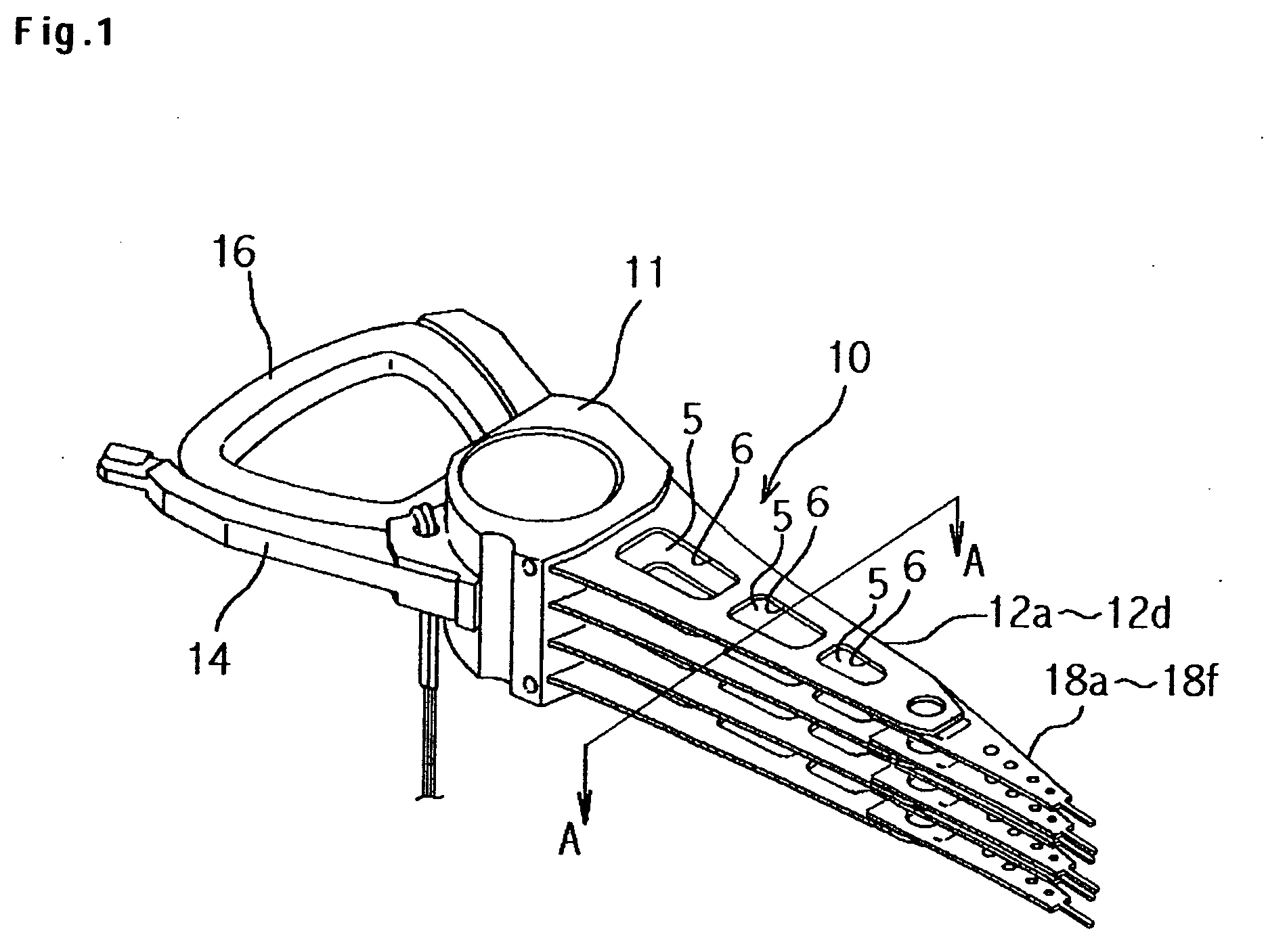
[0013] Accordingly, it is a feature of the present invention to provide a rotating disk storage device capable of suppressing arm fluttering of an actuator arm which constitutes an AHSA and having improved head controllability. It is another feature of the present invention to provide a rotating disk storage device with an actuator arm mounted thereon, the actuator arm having an arm-fluttering-suppressing structure which can be fabricated easily.
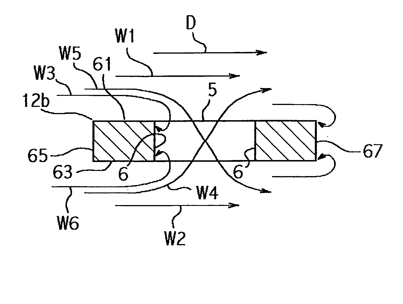
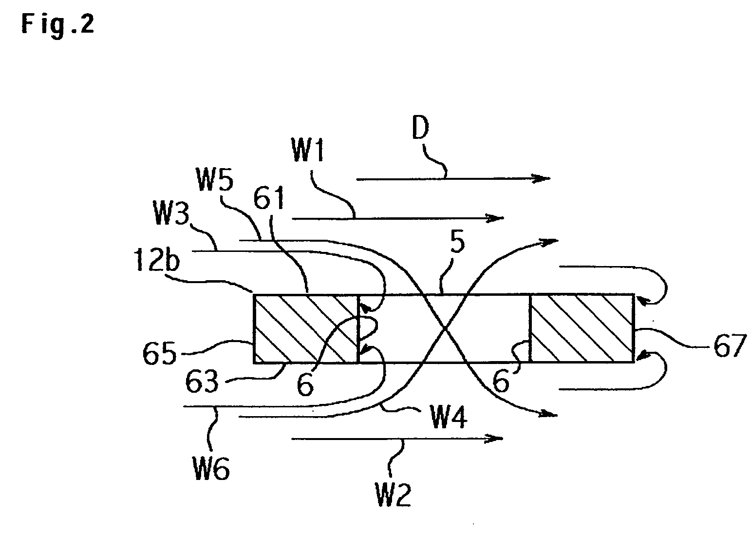
[0016] The main surface of the actuator arm spreads in the pivoting direction and is opposed to the rotating disk storage medium, and an air flow created by rotation of a magnetic disk advances on the main surface. On the main surface, however, the rigid area extends longitudinally centrally of the actuator arm, providing a well-balanced rigid structure. Further, the flow uniformizing area extends longitudinally in adjacency to the rigid area, so that it is possible to diminish a change in flow velocity which is caused by collision of the air flow with a side face of the actuator arm. Since the flow uniformizing area is thinner than the rigid area, it also plays the role of reducing the weight of the entire actuator arm. Thus, in the actuator arm used in embodiments of the present invention, it is not necessary to form a balance aperture to take a weight balance of the entire actuator assembly.
[0017] Forming the flow uniformizing area on both sides of the rigid area is convenient because both weight and rigidity of the actuator arm are well-balanced in a torsional direction. If the rigid area and the flow uniformizing area are formed on each of a first main surface and a second main surface, both main surfaces will exhibit an arm fluttering suppressing effect in the case where the actuator arm is disposed between two stacked rotating disk storage media. If the flow uniformizing area formed on the first main surface and the flow uniformizing area formed on the second main surface are made approximately parallel to each other, it is possible to facilitate machining in comparison with the case where a flow uniformizing area is inclined or is formed as flat surfaces including plural thicknesses. In this connection, when the rigid area includes a substantially flat surface, if the thickness of the flow uniformizing area is set in the range of about 30% to 70% of the thickness of the rigid area, there accrues a convenience in both machining and the balance between both areas.
[0018] In the case where with only the formation of the flow uniformizing area it is virtually impossible to take a predetermined weight balance, it is preferable to form an aperture between the rigid area and a proximal portion of the actuator arm. The proximal portion of the actuator arm is wide in the pivoting direction and high in rigidity because of its proximity to a pivot bearing housing, so even if the aperture is formed, there will be little influence on arm fluttering. If the flow uniformizing area is adjacent to the rigid area along an arcuate boundary, then when the actuator arm moves to an outer periphery of a track especially high in flow velocity, the air flow advances along the arcuate shape, which is more effective in suppressing the arm fluttering. The arcuate shape as the boundary shape permits a larger amount of a thick portion to remain on the proximal side of the actuator arm and is thus convenient for enhancing rigidity. If a slant surface is formed at the boundary between the flow uniformizing area and the rigid area, the air flow can flow from the flow uniformizing area to the rigid area without undergoing any significant change in flow velocity.
[0020] The rigid area and the flow uniformizing area of the actuator arm according to embodiments of the present invention are of a structure suitable for forming the actuator arm by cutting an actuator stock with a milling cutter, the actuator stock being formed by die casting for example. By selecting a metal as the actuator stock and cutting the metal with a milling cutter, it is possible to form an actuator arm unit integrally. By going through the steps of first cutting the flow uniformizing area with a milling cutter and then cutting out an actuator arm simultaneously with subsequent formation of the rigid area, it is possible to facilitate the manufacturing process. Conveniently, a cutting trace with the milling cutter serves as an arcuate boundary between the rigid area and the flow uniformizing area and also serves as a slant surface formed at the boundary. Further, if the area of the flow uniformizing area is set at a value in the range of about 10% to 70% of a total area of the area of the flow uniformizing area and an area of the rigid area, it is possible to display an effect. If it is set in the range of about 30% to 70% of the said total area, there can be attained a structure suitable for reducing the weight of the actuator arm and for ensuring the rigidity thereof.
[0021] According to embodiments of the present invention there could be provided a rotating disk storage device capable of suppressing arm fluttering of an actuator arm as a constituent of an AHSA and having improved head controllability. Further, there could be provided a rotating disk storage device with an actuator arm mounted thereon, the actuator arm having an arm fluttering suppressing structure capable of being fabricated easily.

Problems solved by technology

If the head should undergo an unexpected displacement due to, for example, oscillation or shock while the control unit makes a positional control for the head, a longer time than necessary may be consumed until the head is positioned to a predetermined track, or the head may access an erroneous track.
If a change in flow velocity of the air flow occurs in the vicinity of the actuator arm, the amplitude of the natural oscillation increases and an oscillation called arm fluttering results, which affects the positional control for the head.
With these as background, the prevention of arm fluttering is becoming an important issue.

Method used


Image

  • Rotating disk storage device with suppressed arm fluttering
  • Rotating disk storage device with suppressed arm fluttering
  • Rotating disk storage device with suppressed arm fluttering

Examples


Embodiment Construction

Explanation of Magnetic Disk Drive

[0030] A magnetic disk drive according to an embodiment of the present invention will be described hereinbelow with reference to the accompanying drawings. In the following description and the drawings, the same components are identified by the same reference numerals.

[0031]FIG. 3 is a plan view showing a schematic construction of a magnetic disk drive 20 according to an embodiment of the present invention. In the magnetic disk drive 20, which is an example of a rotating disk storage device, various components are mounted on a base 24 of a disk enclosure. A magnetic disk 22, which is an example of a rotating disk storage medium, is provided on both sides with recording surfaces each having a magnetic layer formed thereon. The magnetic disk 22 is secured to a hub as a constituent of a spindle motor (hereinafter refer to as “SPM”) disposed at a lower position and is adapted to rotate about a spindle shaft 26. In this embodiment five magnetic disks ...


PUM


Abstract

An actuator arm with suppressed arm fluttering is provided. On a main surface of each actuator arm in an actuator arm unit there are formed a rigid area which extends centrally in the longitudinal direction and flow uniformizing areas which are each formed in a substantially flat shape extending longitudinally in adjacency to the rigid area and which are thinner than the rigid area. A balance aperture is not formed in the portion where the flow uniformizing areas and the rigid area are formed, to diminish arm fluttering. Instead of a balance aperture, the flow uniformizing areas also exhibit the effect of reducing the weight of the actuator arm.

Description

CROSS-REFERENCES TO RELATED APPLICATIONS [0001] This application claims priority from Japanese Patent Application No. JP2003-433175, filed Dec. 26, 2003, the entire disclosure of which is incorporated herein by reference. BACKGROUND OF THE INVENTION [0002] The present invention relates to a technique for suppressing oscillation of an actuator head suspension assembly in a rotating disk storage device such as a magnetic disk drive or a magneto-optic disk drive and more particularly to a technique for suppressing fluttering of an actuator arm caused by an air flow generated on a surface of a rotating disk. [0003] A magnetic disk drive as an example of a rotating disk storage device includes a magnetic disk, which has a magnetic layer formed on a surface thereof and is adapted to rotate about a spindle shaft, an actuator head suspension assembly (hereinafter referred to as “AHSA”), and a control unit for controlling the transfer of data and the operation of the device. The AHSA include...

Claims


Application Information

Patent Timeline
IPC IPC(8): G11B5/48G11B5/55G11B21/02G11B21/21G11B21/08G11B21/12G11B25/04G11B33/08G11B33/14
CPCG11B33/08G11B5/4833
Inventor SOGA, EIJIHAYAKAWA, SATOSHICHAWANYA, TAKESHITAKEUCHI, KOHICHI
Owner HITACHI GLOBAL STORAGE TECH NETHERLANDS BV
Learn More