
Control device for mobile robot

a control device and mobile robot technology, applied in the direction of electric programme control, program control, instruments, etc., can solve the problems of resonant vibration, inconvenient presentation of poor flexibility in response to a change in an external force acting on the robot, and the overall center of gravity point of the robot to fluctuate, so as to enhance the arbitrariness enhance the stability of the motion of the mobile robot, and restrict the effect of a desired driving for

Active Publication Date: 2011-06-30
HONDA MOTOR CO LTD
View PDF20 Cites 60 Cited by
  • Summary
  • Abstract
  • Description
  • Claims
  • Application Information

AI Technical Summary

Benefits of technology

[0020]As a result, the first aspect of the invention makes it possible to stably implement a desired motion of the mobile robot while restraining the mobile robot from tottering.
[0093]Thus, the sixth aspect of the invention makes it possible to compensate for an influence of an error or the like of a model on which the aforesaid expression 01 is based, thereby preventing a mismatch between a contact portion external force desired value corresponding to a desired driving force determined according to the aforesaid expression 01 and an external force actually acting on the contact portion. This permits enhanced stability of the motion of the robot.

Problems solved by technology

According to the position control described above, the actual displacement amount of a joint is maintained to be constant as long as the desired displacement amount of the joint remains constant, thus inconveniently presenting poor flexibility in response to a change in an external force acting on the robot.
This easily causes the overall center-of-gravity point of the robot to fluctuate.
Especially when the position of the overall center-of-gravity point of the robot changes in a vertical direction, the overall center-of-gravity point frequently vibrates in the vertical direction accordingly, possibly leading to a resonant vibration.
Such a vibration may make it difficult to stably accomplish a desired motion of the robot.

Method used


Image

  • Control device for mobile robot
  • Control device for mobile robot
  • Control device for mobile robot

Examples


first embodiment

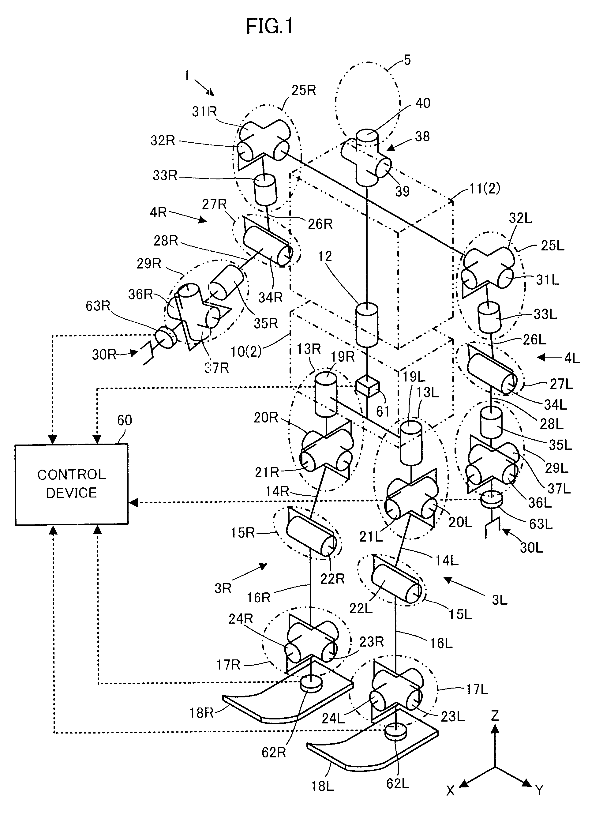
[0100]The following will describe a first embodiment of the present invention with reference to FIG. 1 to FIG. 5.

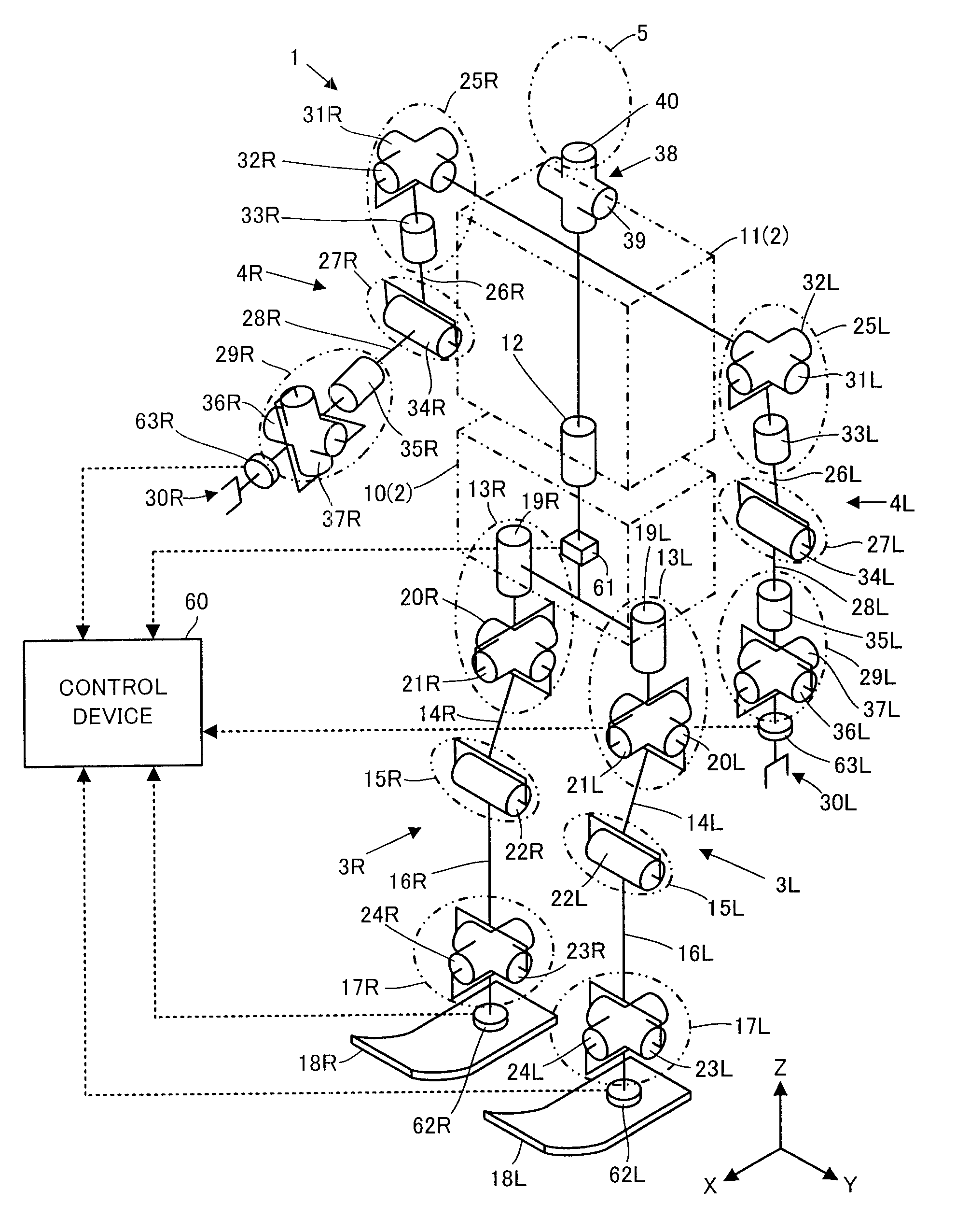
[0101]FIG. 1 schematically illustrates the skeleton framework of a mobile robot illustrated in the present embodiment. This mobile robot 1 (hereinafter referred to simply as the robot 1) is a bipedal mobile robot as a legged mobile robot. The robot 1 is roughly constituted of a body link 2, a pair of right and left leg links 3R, 3L, a pair of right and left arm links 4R, 4L, and a head 5.

[0102]In the present description, a member on the right side observed facing to the front of the robot 1 or a variable indicating a quantity associated with the member will be suffixed by a character “R,” while a member on the left side observed facing to the front of the robot 1 or a variable indicating a quantity associated with the member will be suffixed by a character “L.” However, the characters “R” and “L” may be omitted unless it is particularly necessary to distinguish between th...

second embodiment

[0332]A second embodiment of the present invention will now be described with reference mainly to FIG. 6.

[0333]The present embodiment differs from the first embodiment in the method for setting a contact portion representative element in the processing by a desired joint driving torque determiner 72 of a control device 60. Accordingly, in the processing by a desired joint driving torque determiner 72, the processing by a contact portion Jacobian matrix determiner 82, a control input determiner 85, and a compliance controller 86 is partly different from that of the first embodiment. The rest of the processing by the desired joint driving torque determiner 72 (the processing by a basic parameter group determiner 81, a state amount Jacobian matrix determiner 83, and a state amount desired value determiner 84), and the processing by a gait generator 71 and a joint drive controller 73 is the same as that in the first embodiment.

[0334]Therefore, the description of the present embodiment w...


PUM


Abstract

A control device for a mobile robot, in which the desired value of a motion state amount of a mobile robot includes at least the desired value of a vertical component of a first-order differential value of the translational momentum of the entire mobile robot. The desired value is determined by a state amount desired value determiner such that the observed value of the vertical position of an overall center-of-gravity point of the mobile robot is converged to a predetermined desired value according to a feedback control law. A control input determiner carries out the processing of inverse dynamics calculation, using the desired value of the motion state amount thereby to determine the desired driving force for each joint. The operation of an actuator is controlled on the basis of the determined desired driving force.

Description

BACKGROUND OF THE INVENTION[0001]1. Field of the Invention[0002]The present invention relates to a control device for a mobile robot, such as a legged mobile robot.[0003]2. Description of the Related Art[0004]As a technique for controlling a legged mobile robot, such as a bipedal walking robot, there has been generally known so-called position control proposed in, for example, Japanese Patent Application Laid-Open No. 5-305579 by the applicant of the present application. According to the disclosed technique, the desired displacement amount of each joint of a robot is sequentially determined on the basis of a desired motion of the robot (e.g., the trajectory of a desired position of the distal end of a leg of the robot), and then the actuator of each joint is drivably controlled so as to cause an actual displacement amount to coincide with the desired displacement amount.[0005]According to the position control described above, the actual displacement amount of a joint is maintained t...

Claims


Application Information

Patent Timeline
Patent Type & Authority Applications(United States)
IPC IPC(8): B25J13/00
CPCB62D57/032
Inventor ORITA, ATSUOKANAZAWA, MASAO
Owner HONDA MOTOR CO LTD
Learn More