
Apparatus for replacing welding tip of welder and apparatus for supplying same

a technology of welding tip and supply apparatus, which is applied in the direction of manufacturing tools, electrode features, transportation and packaging, etc., can solve the problems of deformation, all the manufacturing lines of the automated factory may be affected, and the work efficiency may be degraded, so as to prevent any error, enhance productivity, and stably implement the

Active Publication Date: 2017-04-20
CHOI OK
View PDF9 Cites 0 Cited by
  • Summary
  • Abstract
  • Description
  • Claims
  • Application Information

AI Technical Summary

Benefits of technology

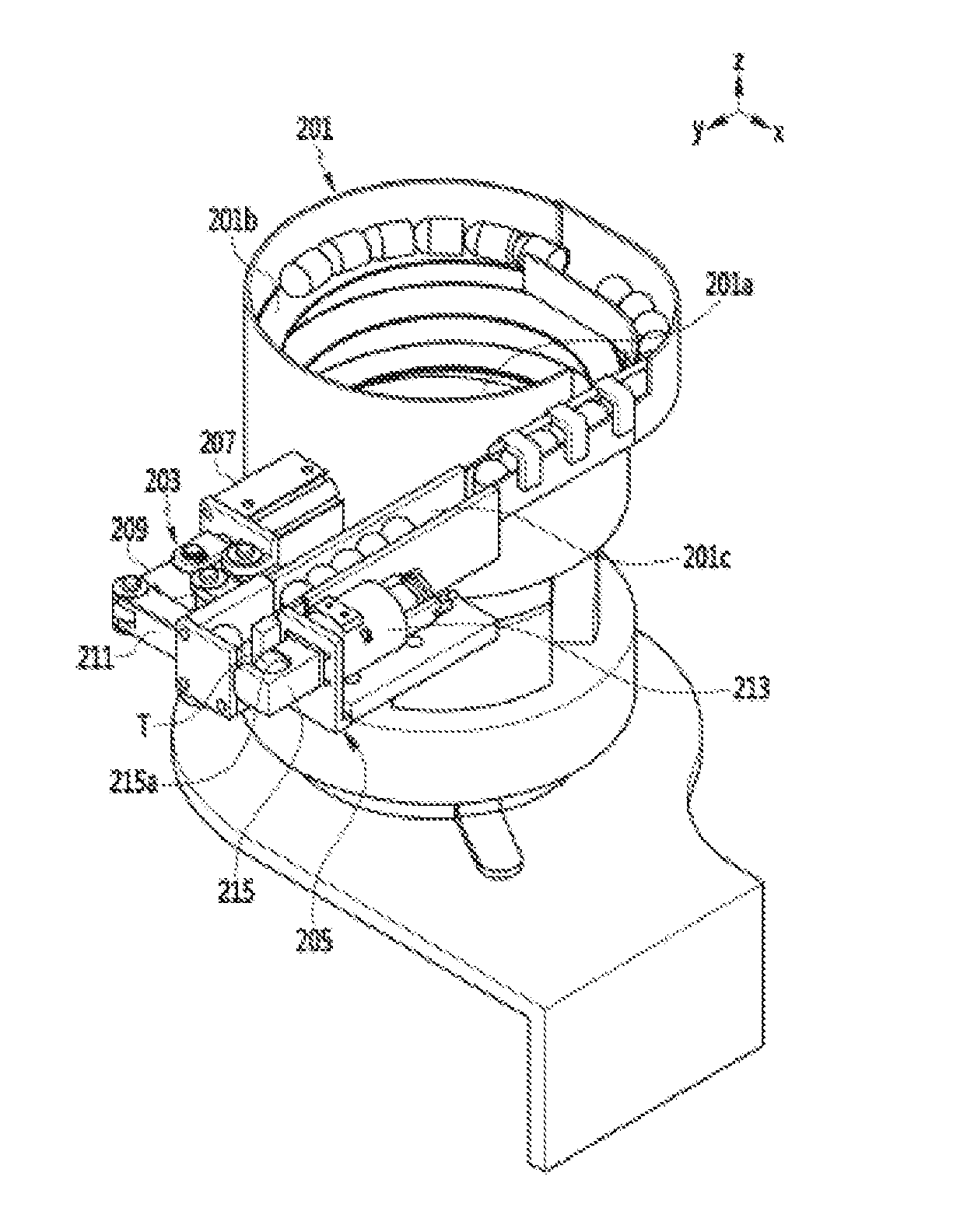
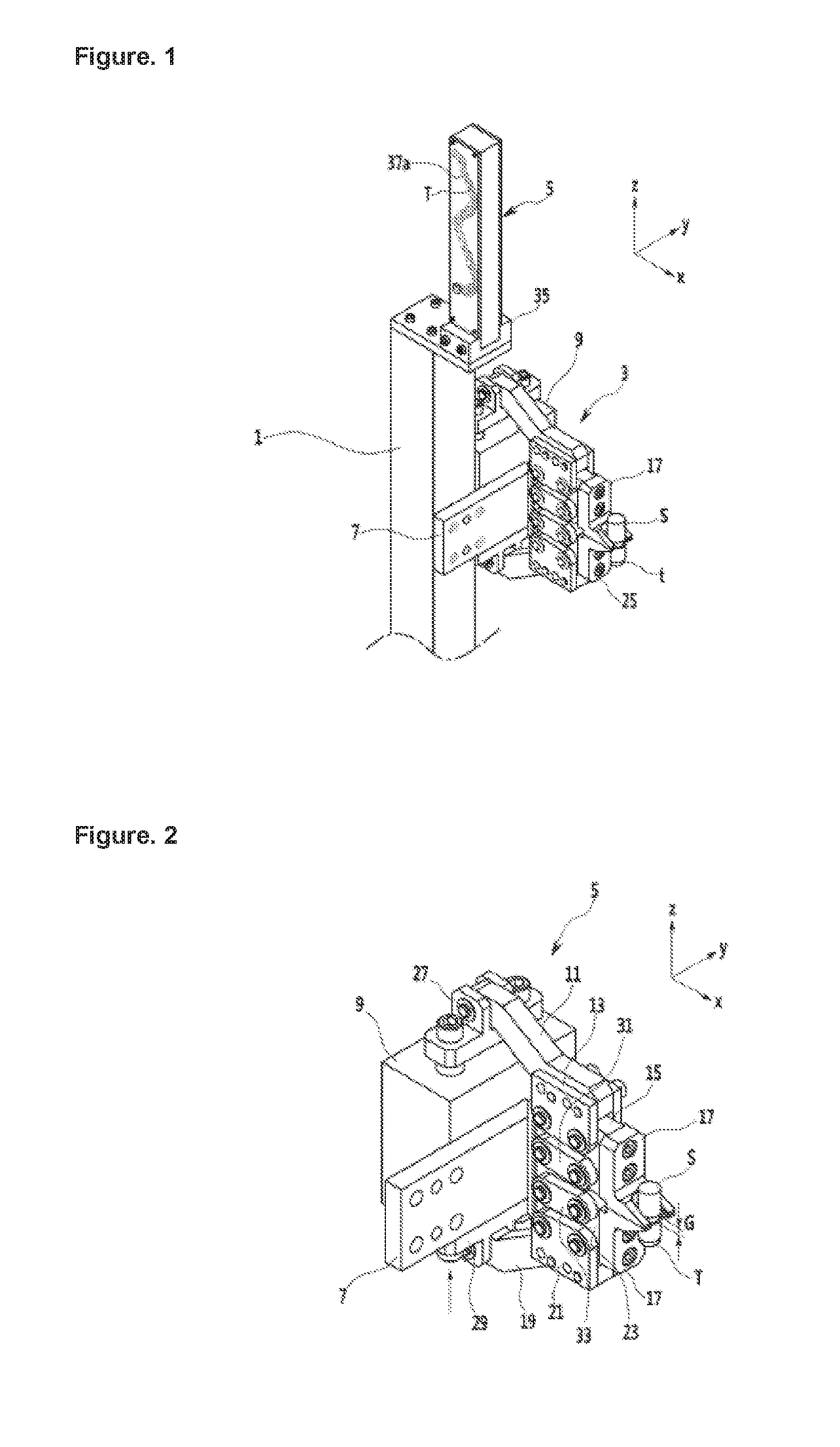
The present invention provides a welding tip supplying apparatus that can stably remove the welding tip from the shank and accommodate more welding tips in a limited space. The apparatus includes a welding tip storing groove and a direction changing part, making it easy to confirm the amount of welding tips accommodated. The apparatus also includes a welding tip supplying box with a transparent plate to prevent error during welding tip replacing work. Additionally, the apparatus allows for stable replacement of welding tips and prevents welding tip replacing errors. The direction of the discharge port of the apparatus can be switched to reduce the replacing work time and increase productivity. The apparatus is convenient for workers to attach and detach from the support part, improving work efficiency.

Problems solved by technology

If such a welding tip is repeatedly used, a deformation may occur, for which it needs to periodically replace the welding tip.
When this welding tip is exchanged, a replacing work time should be shortened, and a welding tip replacing work should be stably carried out; however such conditions are not actually satisfied, thus causing a problem.
If a welding tip is not provided at a conventional welding tip supplying apparatus, a welding robot cannot recognize the absence of the welding tip, which may make an error when replacing a welding tip, whereby a work efficiency may be degraded.
In this conventional welding tip supplying apparatus for a welder, it needs to periodically replace the accommodation case in which the welding tips are accommodated, thus causing inconvenience, and if the accommodation case in which the welding tips are accommodated, are not replaced in time, all the manufacturing lines of the automated factory may be affected.

Method used


Image

  • Apparatus for replacing welding tip of welder and apparatus for supplying same
  • Apparatus for replacing welding tip of welder and apparatus for supplying same
  • Apparatus for replacing welding tip of welder and apparatus for supplying same

Examples


second embodiment

[0190]In the embodiment of the present invention, the rotation member 225 and the elastic member 227 may allow to fix the welding tip (T) accommodated in the accommodation groove part 215a. Since the welding tip (T) can be fixed in place without separately installing the ball plunger 217 at the welding tip holding part 215, the more reliable configuration can be implemented in the present invention.

[0191]FIG. 26 is a view for describing a third example of the embodiment of the present invention while showing the fixing part 205 of the apparatus for supplying a welding tip of a welder.

[0192]Since the description of the third example of the embodiment of the present invention is same as the contents of the descriptions of the previous embodiment, the same descriptions will be omitted, and only a difference will be described. In the third example of the embodiment of the present invention, the same components as in the descriptions of the embodiment will be given the same reference num...

third embodiment

[0194]Since the operational procedure of the third example of the embodiment of the present invention is similar with the second example, the descriptions thereof will be omitted. the present invention shows that the present invention may be implemented in various forms.

[0195]FIG. 27 is a view for describing a fourth example of the embodiment of the present invention, while showing the fixing part 205 of the apparatus for supplying a welding tip of a welder. The descriptions of the fourth example of the embodiment of the present invention is same as the descriptions of the previous embodiment, so only a difference will be described. The same components as in the descriptions of the previous embodiment will be given the same reference numbers as the reference numbers of the previous embodiment.

[0196]The welding tip holding part 215 of the fixing part 205 of the fourth example of the embodiment of the present invention may include a fixing member 223, and an elastic plate 233. The ela...


PUM

PropertyMeasurementUnit
heightsaaaaaaaaaa
elasticaaaaaaaaaa
timeaaaaaaaaaa

Abstract

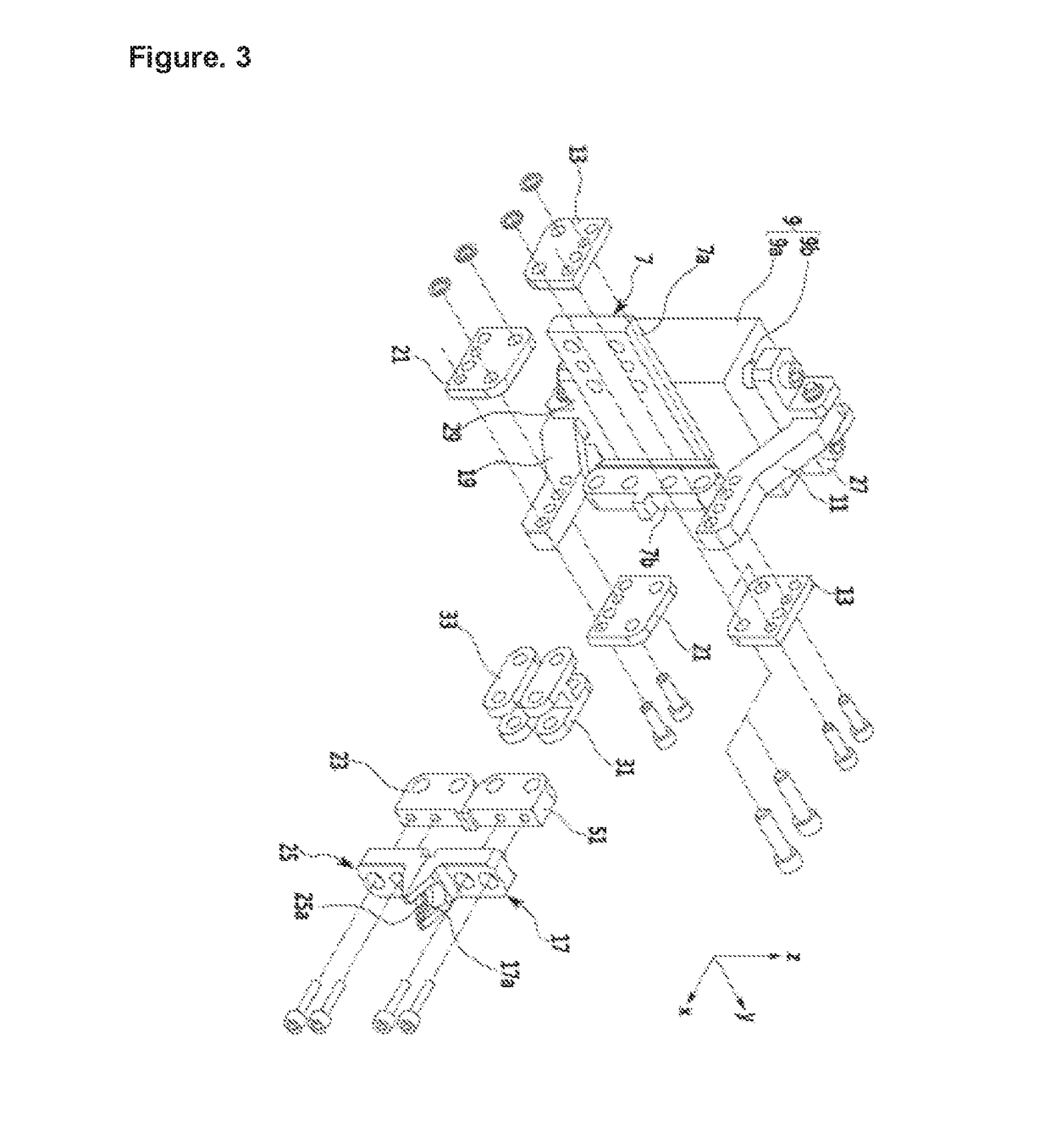
Disclosed are an apparatus for supplying a welding tip of a welder and an apparatus for replacing the same, which can automatically supply or replace a welding tip of a welding robot that is used in a vehicle body production factory, etc. The apparatus for replacing a welding tip of a welder of the present invention comprises: a fixed bracket secured to a support; an actuator coupled to the fixed bracket; a first moving member that is moved by the actuator; a second moving member coupled to the first moving member and hingedly coupled to the fixed bracket; a third moving member hingedly coupled to the second moving member; a first welding tip removal member coupled to the third moving member to separate a welding tip coupled to a shank; a fourth moving member that is moved by the actuator and is disposed opposite to the first moving member; a fifth moving member coupled to the fourth moving member and hingedly coupled to the fixed bracket; a sixth moving member coupled to the fifth moving member; and a second welding tip removal member that is coupled to the sixth moving member and moves in relation to the first welding tip removal member.

Description

TECHNICAL FIELD[0001]The present invention relates to a welding tip supplying apparatus for a welder, wherein a welding tip of a welding robot used at a vehicle body manufacturing factory, etc. can be automatically replaced or supplied.BACKGROUND ART[0002]A spot welding method which uses an automatic robot welder, is mainly used at a manufacturing line, for example, a vehicle manufacturing line which is able to manufacture a predetermined product through a mass production method. This spot welding method has a good work efficiency since a heating time is short. Since the spot welding method has a narrow heating range, a residual stress or a deformation occurs less, which may provide a high stability to a welded portion.[0003]A welding gun used for a spot welding method is mounted on a robot, and a shank is installed with the front ends thereof being disposed opposing to each other, and a welding tip at which a welding is actually carried out, is installed at an end portion of the sh...

Claims


Application Information

Patent Timeline
Patent Type & Authority Applications(United States)
IPC IPC(8): B23K11/30B23K11/11
CPCB23K11/11B23K11/3072B23K11/36B65G47/90B65G47/904Y10T483/17B65G47/02B65G47/1421
Inventor CHOI
Owner CHOI OK
Learn More