
System and method of automatic destination selection

a technology of automatic destination selection and destination selection, applied in the field of location-based services, can solve the problems of troublesome old or inaccurate traffic information, difficult to predict traffic congestion, and inability to meet the needs of users,

Active Publication Date: 2011-06-30
HUAWEI TECH CO LTD
View PDF16 Cites 128 Cited by
  • Summary
  • Abstract
  • Description
  • Claims
  • Application Information

AI Technical Summary

Benefits of technology

The patent text describes a system and method for providing navigation information to mobile devices based on data collected from various sources such as radio, television, and online news sources. The system uses a route representation system to determine the best route between an origin and destination based on various measures such as shortest, fastest, and simplest. The text also describes various user interface elements and applications that can be provided on mobile devices, such as traffic notification, search functionality, and social media integration. The technical effects of the patent text include improved traffic information and better user experience for location-based services on mobile devices.

Problems solved by technology

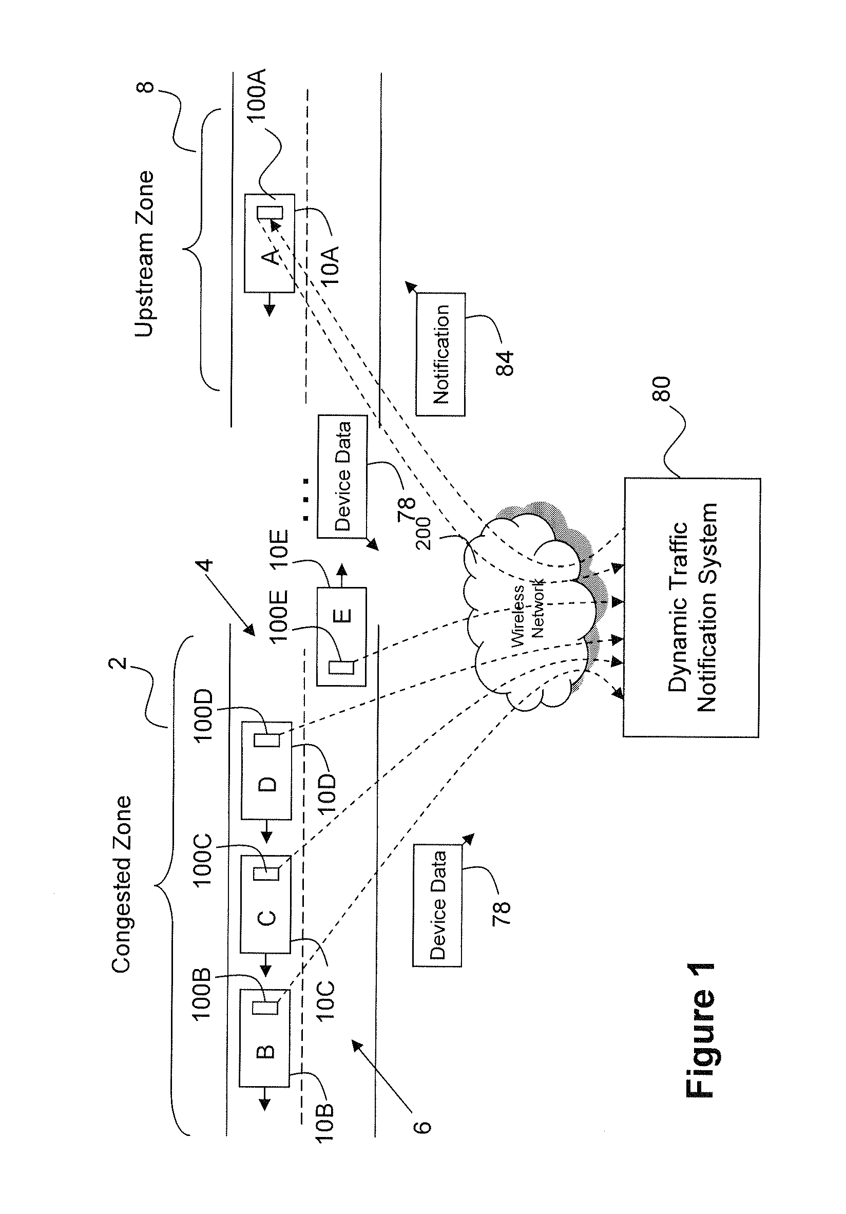
Due to the nature of such events traffic congestion can be difficult to predict.
Although radio, television, and online news sources can provide traffic information gathered using various techniques such as highway cameras, phone-in traffic tips, satellite imagery, and road sensors; this information is stale and / or inaccurate.
Old or inaccurate traffic information can be troublesome for various reasons.
For example, an alternate traffic route, which may be less convenient, is chosen due to a traffic report indicating that a traffic problem exists, which problem has since been alleviated.
This can cause a commuter to take a less optimal route, which can waste fuel, cause them to be late, and cause congestion on side-roads.

Method used


Image

  • System and method of automatic destination selection
  • System and method of automatic destination selection
  • System and method of automatic destination selection

Examples


Embodiment Construction

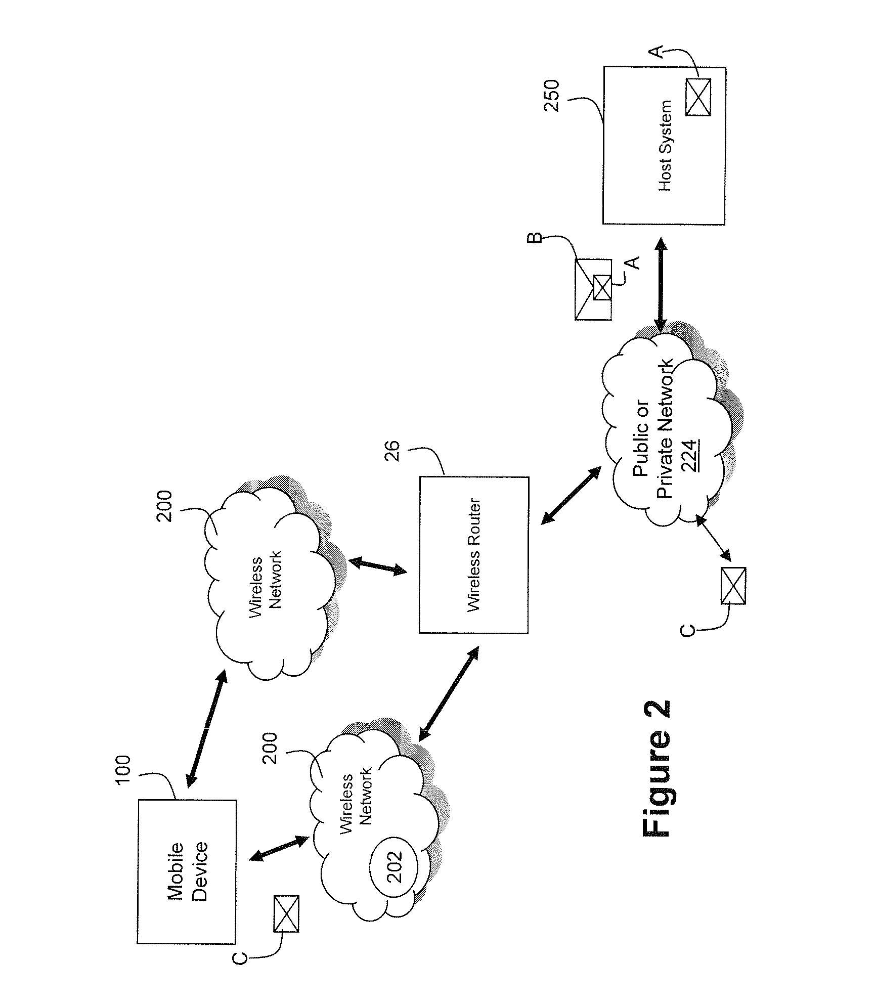
less router shown in FIG. 2.

[0018]FIG. 10 depicts a flow diagram illustrating exemplary operations performed by a traffic notification system for preparing and providing a traffic notification to a mobile device.

[0019]FIG. 11 depicts a method for location prediction for route determination and ETA determination.

[0020]FIG. 12 depicts an example start screen of a navigation function that can provide functionality and use technology described above.

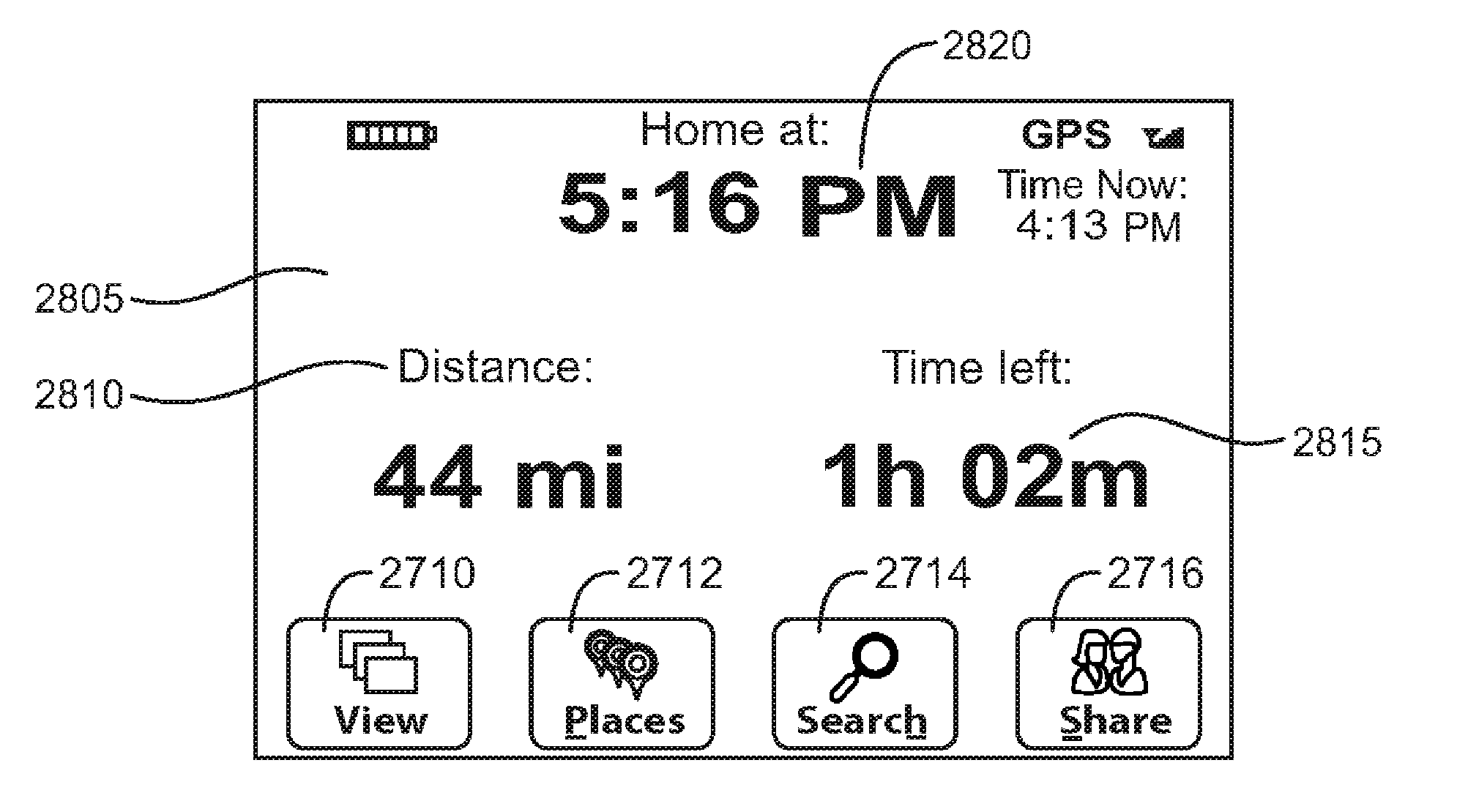
[0021]FIG. 13 depicts an example display of ETA information.

[0022]FIG. 14 depicts an example user interface element.

[0023]FIG. 15 depicts a user interface element within the navigation application.

[0024]FIG. 16 depicts an example user interface element relating to route representation.

DETAILED DESCRIPTION

[0025]It will be appreciated that for simplicity and clarity of illustration, where considered appropriate, reference numerals may be repeated among the figures to indicate corresponding or analogous elements. In addition, numerous specific ...


PUM


Abstract

When a user enters, initializes, or otherwise starts using a navigation function, such as a navigation function on a mobile phone or a stand-alone device, a destination is automatically selected for route generation and production of a navigation output (e.g., an Estimated Time of Arrival (ETA) at the destination). The destination is selected based on current proximity to a location that has a pre-defined destination associated with it. Such pre-defined destination usually is associated with the location by the user. A time of day criteria can also be imposed, such as requiring that the time of day either by in the morning or afternoon, a work day, or a holiday, or the opposite. In one example, locations proximate a work place can be associated with home as a pre-defined destination, and vice versa. A time of day criteria can be imposed, such that even if proximate work and it is in the morning, a route and ETA to home will not be generated.

Description

CROSS REFERENCE TO RELATED APPLICATIONS[0001]This application claims priority from U.S. Provisional Pat. App. Ser. No. 61 / 290,570, filed on Dec. 29, 2009, entitled “SYSTEM AND METHOD OF AUTOMATIC DESTINATION SELECTION”, the contents of which are incorporated herein in their entirety for all purposes.BACKGROUND[0002]1. Technical Field[0003]The following relates generally to location based services (LBS) for mobile devices, and in particular to systems and methods for providing navigation information, routes, Estimated Time of Arrival (ETA) information, search functionality, and other related functionality on mobile devices.[0004]2. Related Art[0005]Rush hour traffic volume, road construction, vehicular collisions, and roadside emergencies are just a few examples of the various events and circumstances that can cause traffic congestion. Due to the nature of such events traffic congestion can be difficult to predict. Although radio, television, and online news sources can provide traff...

Claims


Application Information

Patent Timeline
Patent Type & Authority Applications(United States)
IPC IPC(8): G01C21/36
CPCG01C21/3617G01C21/3492G01C21/3691G01C21/3484G01C21/3407G01C21/3605
Inventor FINK, DANIEL EDWARD
Owner HUAWEI TECH CO LTD
Learn More