Block management method of a non-volatile memory

a management method and non-volatile memory technology, applied in the direction of memory adressing/allocation/relocation, instruments, error detection/correction, etc., can solve the problems of data loss, low-cost mlc flash memory performance decline, and conventional management mechanisms are either ineffective in managing low-cost mlc flash memory or very inefficient in doing so. , to achieve the effect of improving the garbage collection performance of a non-volatile memory storage system,

Active Publication Date: 2011-06-30
NAT TAIWAN UNIV
View PDF9 Cites 18 Cited by
  • Summary
  • Abstract
  • Description
  • Claims
  • Application Information

AI Technical Summary

Benefits of technology

[0022]As described above, the technique provided by the present invention improves the garbage collection performance of a non-volatile memory storage system. In addition, according to the present invention, the address translation table contained in each predetermined lined physical page set helps to increase the boot up speed. Moreover, pointers between physical block sets corresponding to the same logical block help to speed up the recovery from system crash or power failure.

Problems solved by technology

However, the performance of flash memory decreases along with the fabrication cost thereof.
Thereby, the conventional management mechanisms are either incapable of managing low-cost MLC flash memory or very inefficient in doing so.
However, in a storage system adopting such a mechanism, data may be lost when the system fails or the power supply is cut off.
As a result, the storage system lacks data consistency.

Method used


Image

  • Block management method of a non-volatile memory
  • Block management method of a non-volatile memory
  • Block management method of a non-volatile memory

Examples


Embodiment Construction

[0028]Reference will now be made in detail to the present preferred embodiments of the invention, examples of which are illustrated in the accompanying drawings. Wherever possible, the same reference numbers are used in the drawings and the description to refer to the same or like parts.

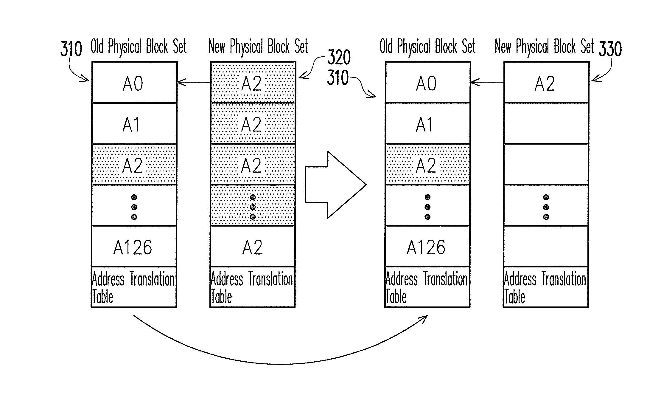
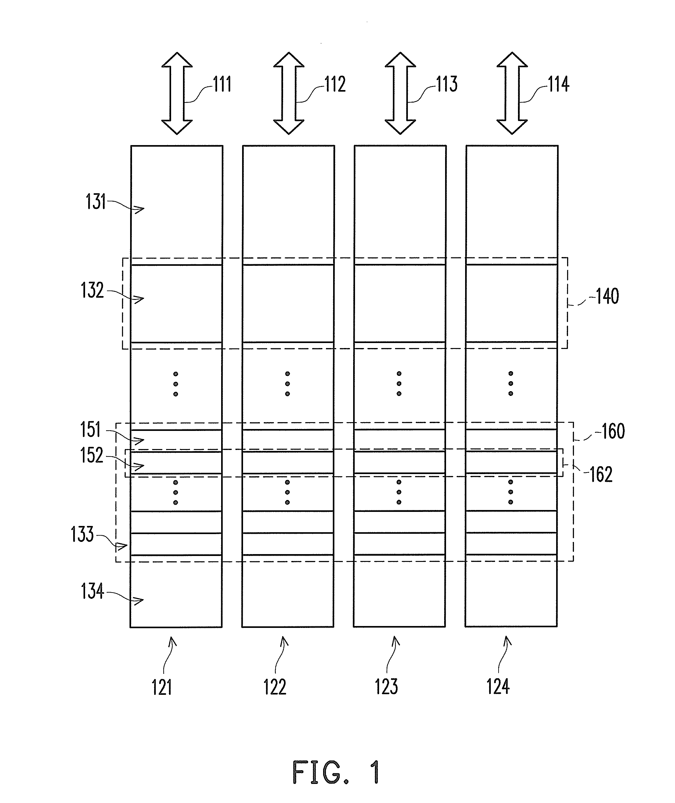
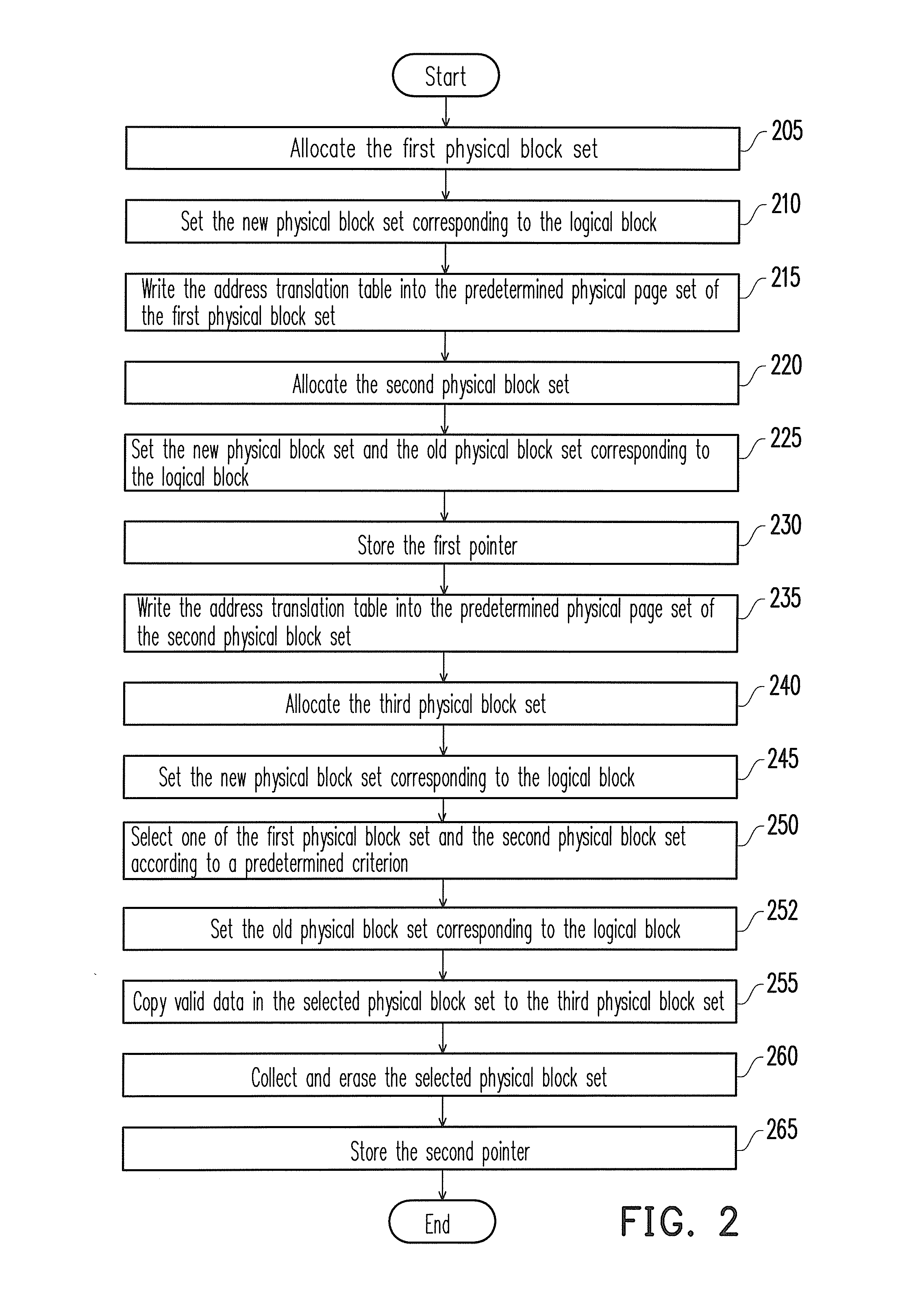
[0029]FIG. 1 is a diagram of a non-volatile memory storage system according to an embodiment of the present invention. Referring to FIG. 1, the non-volatile memory storage system includes hardware channels 111-114 and non-volatile memory chips 121-124. The hardware channels 111-114 are buses configured to transmit memory data and control signals. In the present embodiment, the non-volatile memory chips 121-124 are multi-level cell (MLC) flash memory chips. However, the present invention is not limited thereto, and in other embodiments of the present invention, the non-volatile memory chips 121-124 may also be other types of non-volatile memory chips. Each of the hardware channels 111-114 is coupled t...


PUM


Abstract

A block management method applicable to a non-volatile memory storage system is provided. The non-volatile memory storage system includes a plurality of chips. Each chip includes a plurality of physical blocks. The physical blocks form a plurality of physical block sets. Each logical block in a logical space corresponds to at most two physical block sets. In the block management method, when a logical block corresponds to two physical block sets filled with data and more data is to be written, a free physical block set is allocated for storing the data. Then, one of the two physical block sets corresponding to the logical block is selected according to a predetermined criterion. The valid data in the selected physical block set is copied into the free physical block set. Next, the selected physical block set is erased and collected to the pool of free physical block sets.

Description

CROSS-REFERENCE TO RELATED APPLICATION[0001]This application claims the priority benefit of Taiwan application Ser. No. 98144803, filed on Dec. 24, 2009. The entirety of the above-mentioned patent application is hereby incorporated by reference herein and made a part of specification.BACKGROUND OF THE INVENTION[0002]1. Field of the Invention[0003]The present invention generally relates to a non-volatile memory storage system, and more particularly, to a block management method of a non-volatile memory.[0004]2. Description of Related Art[0005]The low fabrication cost of flash memory has been a major motivation in the development of flash memory. A flash memory chip is composed of blocks, and each of the blocks is further composed of pages. Each block is the basic data erasing unit, while each page is the basic data accessing unit. Once data is written into a page, no other data can be written into the same page until the block corresponding to the page is entirely erased. Thus, data ...

Claims


Application Information

Patent Timeline
Patent Type & Authority Applications(United States)
IPC IPC(8): G06F12/02G06F12/00G06F12/16
CPCG06F11/1441G06F2212/7205G06F12/0246
Inventor CHANG, YUAN-HAOKUO, TEI-WEI
Owner NAT TAIWAN UNIV
Why Eureka
Try Eureka