Stringed Instrument, Manufacturing Method and Apparatus Thereof

Active Publication Date: 2011-07-07
TOKYO METROPOLITAN IND TECH RES INST
View PDF9 Cites 27 Cited by
  • Summary
  • Abstract
  • Description
  • Claims
  • Application Information

AI Technical Summary

Benefits of technology

[0080]According to the apparatus of claim 20, it is possible to achieve performances (sound volume, acoustic quality, and acousmato) of an instrument satisfying a preference of a player and a purpose of performance by the manufactured stringed instrument because the stringed instrument is manufactured by the manufacturing method according t

Problems solved by technology

To begin with, it is almost impossible to design and manufacture the stringed instrument such that the sound c

Method used


Image

  • Stringed Instrument, Manufacturing Method and Apparatus Thereof
  • Stringed Instrument, Manufacturing Method and Apparatus Thereof
  • Stringed Instrument, Manufacturing Method and Apparatus Thereof

Examples


first embodiment

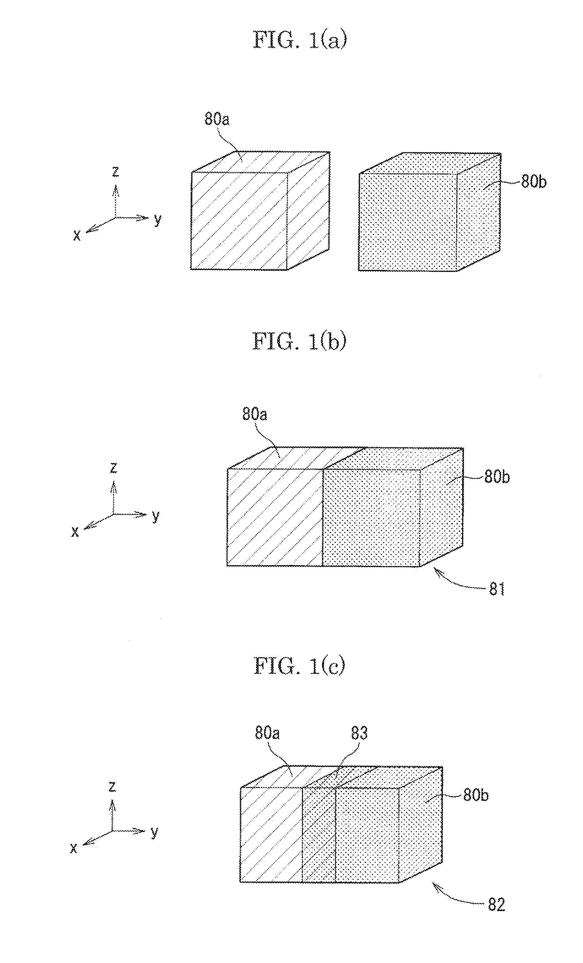
[0206]FIGS. 4(a) and 4(b) are explanatory views illustrating an example manufacturing the resonance box portion of the violin by the contact bonding method using plural laser irradiation conditions. FIG. 4(a) is a front view of the resonance box portion, and FIG. 4(b) is a right side view of the resonance box portion. In FIGS. 4(a) and 4(b), the resonance box portion 401 is illustrated, and it is described on an assumption that the resonance box portion 401 is integrally formed by using the contact bonding method described by using FIG. 1(b). When the resonance box portion 401 is manufactured as an example of the present invention, a top plate portion 402b integrally including a dot-hatched purfling is manufactured by selectively using the laser irradiation condition B represented in the table 1, and the other oblique-hatched portion group 402a (the back plate portion integrally including the purfling, the side plate portions, the blocks, the linings, the bass bar, and the saddle) i...

second embodiment

[0207]FIGS. 5(a) and 5(b) are explanatory views illustrating an example manufacturing the top plate portion of the violin by using plural laser irradiation conditions. FIG. 5(a) is the explanatory view when two kinds of laser irradiation conditions are used. FIG. 5(b) is the explanatory view when three kinds of laser irradiation conditions are used.

[0208]FIG. 5(a) illustrates that a top plate portion 511 integrally including the purfling is divided into approximately symmetrical two parts, and the top plate portion 511 is integrally manufactured by selectively changing the laser irradiation conditions respectively to a part 511a (for example, the three-dimensional desired area) manufactured under the laser irradiation condition A and a part 511b (the three-dimensional adjacent area in the above-stated example) manufactured under the laser irradiation condition B by using the contact bonding method. As a result, it is designed that the vibrational characteristics of the stringed inst...

third embodiment

[0212]FIG. 6 is a schematic diagram of the three-dimensional structure in which an outside contour portion is solidified, and raw material powder remains as it is in an (enclosed) space portion 153a inside thereof, which is capable of being manufactured by using the additive fabrication method. To simplify the description, a rectangular solid three-dimensional structure 150 in FIG. 6 is represented under a state in which a corner portion 151 is tentatively cut, and the space portion 153a inside the rectangular solid three-dimensional structure 150 is illustrated. The additive fabrication method selectively sintering the raw material powder is a method in which a desired three-dimensional structure is manufactured by laminating each cross section of the three-dimensional structure to be manufactured one layer by one layer. Accordingly, it is possible to manufacture the three-dimensional structure under a state in which the outside contour portion 152 with thin thickness is solidified...


PUM

PropertyMeasurementUnit
Ratioaaaaaaaaaa
Areaaaaaaaaaaa
Vibrational spectrumaaaaaaaaaa

Abstract

The present invention provides a stringed instrument capable of corresponding to a preference of a player of the stringed instrument, a purpose of performance, and so on as much as possible. A resonance box portion fabricated by an additive fabrication method and a neck portion protruding from the resonance box portion are included, and material constants at a desired area of the resonance box portion is made different from material constants at an adjacent area adjacent to the desired area step by step or continuously. Vibrational characteristics of the instrument are changed by the partial difference of the material constants, and thereby, the stringed instrument capable of corresponding to the preference of the player, the purpose of the performance, and so on is provided.

Description

BACKGROUND OF THE INVENTION[0001]1. Field of the Invention[0002]The present invention relates to a stringed instrument, a manufacturing method of the stringed instrument, and a stringed instrument manufacturing apparatus.[0003]2. Description of the Related Art[0004]FIGS. 13(a) to 13(c) are structural drawings of a violin as an example of stringed instruments of the present invention. FIG. 13(a) is a front view of the violin, FIG. 13(b) is a right side view of the violin, and FIG. 13(c) is an M-M′ sectional view of the violin illustrated in FIG. 13(b). An arrow 70 defining a longitudinal direction of the violin, an arrow 71 defining a width direction of the violin, and an arrow 72 defining a thickness direction of the violin are drawn in each of FIGS. 13(a), 13(b), 13(c) to simplify the explanation.[0005]In the present description, detailed names of respective portions of the violin are referred to later-described non-patent documents 1, 2, 3, 4. A whole of a violin 1 in FIGS. 13(a) ...

Claims


Application Information

Patent Timeline
IPC IPC(8): G10D3/02B29C65/00B29C65/14
CPCG10D1/00G10D3/02G10D1/005B22F2998/10B33Y80/00G10D3/22Y02P10/25G10D1/02B22F10/43B22F10/28B22F10/36B22F10/66B22F10/68B22F10/80
Inventor YOKOYAMA, YUKIO
Owner TOKYO METROPOLITAN IND TECH RES INST
Why Eureka
Try Eureka