Portable device for generating electric power

a portable device and electric power technology, applied in the direction of electric generator control, renewable energy generation, greenhouse gas reduction, etc., can solve the problems of windmill repair and maintenance, high cost of operating the complex, and heavy devices

Inactive Publication Date: 2011-07-07
IQ ENERGY
View PDF22 Cites 18 Cited by
  • Summary
  • Abstract
  • Description
  • Claims
  • Application Information

AI Technical Summary

Benefits of technology

[0012]At least a portion of the sail may generate electricity from sunlight. The system may include a fairing at the leading edge of the mast, the fairing being secured to the sail. The fairing may fold over the mast and may be attached to the sail. The system may include leading edge formers within the faring. The sail may include at least one elongated opening at which the fairing is slidably connected to the sail. The fairing may include at least one elongated opening on either side of the fairing through which the sail is slidably mounted.

Problems solved by technology

The devices tend to be heavy, are prone to breaking down, and are fixed into place at a set location.
Repair and maintenance of a windmill, for example, is often dangerous, as it is carried out many feet above the ground, and the cost of operating the complex can be very high.

Method used


Image

  • Portable device for generating electric power
  • Portable device for generating electric power
  • Portable device for generating electric power

Examples


Embodiment Construction

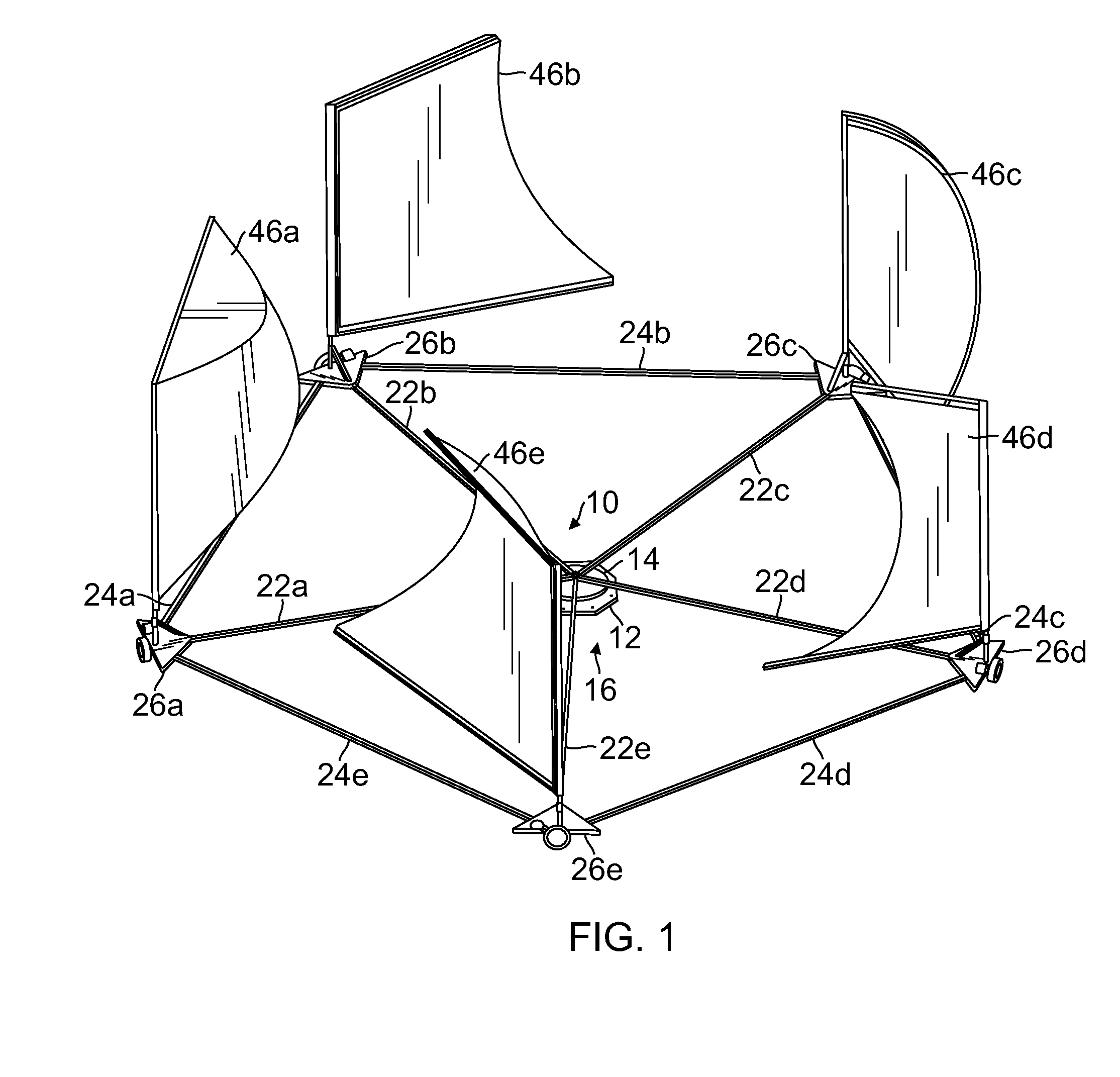
[0089]Referring now to the drawings, which are provided by way of example and not limitation, one embodiment of a portable electric energy generation system is illustrated in FIG. 1. The generator includes a fixed based assembly 10 having a bottom plate with stakes 12 and an upper rotating portion 14. The fixed base assembly 10 also includes slip rings and bearings 16 (FIG. 12).

[0090]Extending from the fixed base assembly 10 are radial struts 22a-e. These radial struts interconnect with an outer frame having circumferential struts 24a-e. The circumferential struts 24a-e interconnect with respective apex plate assemblies 26a-e.

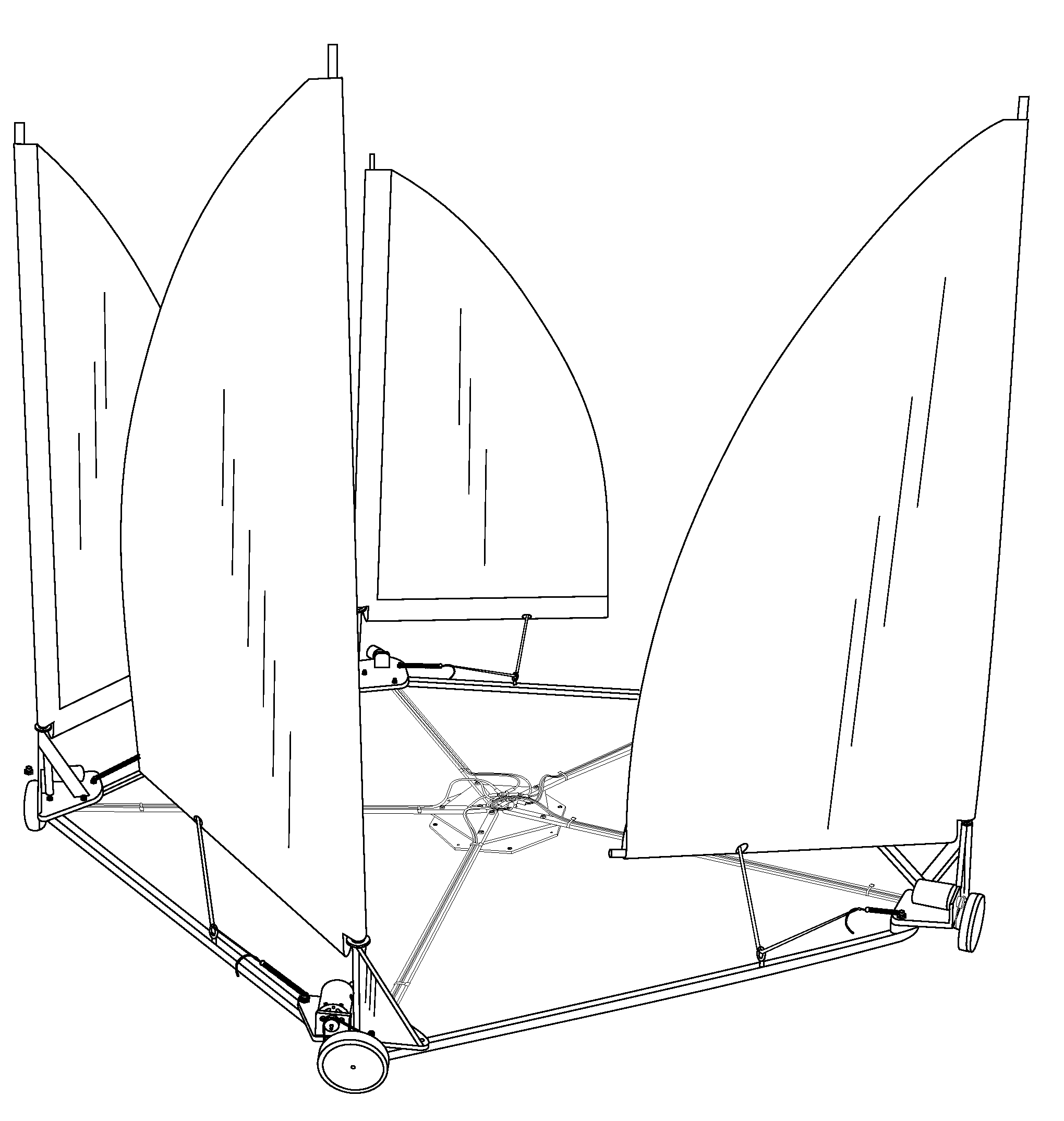
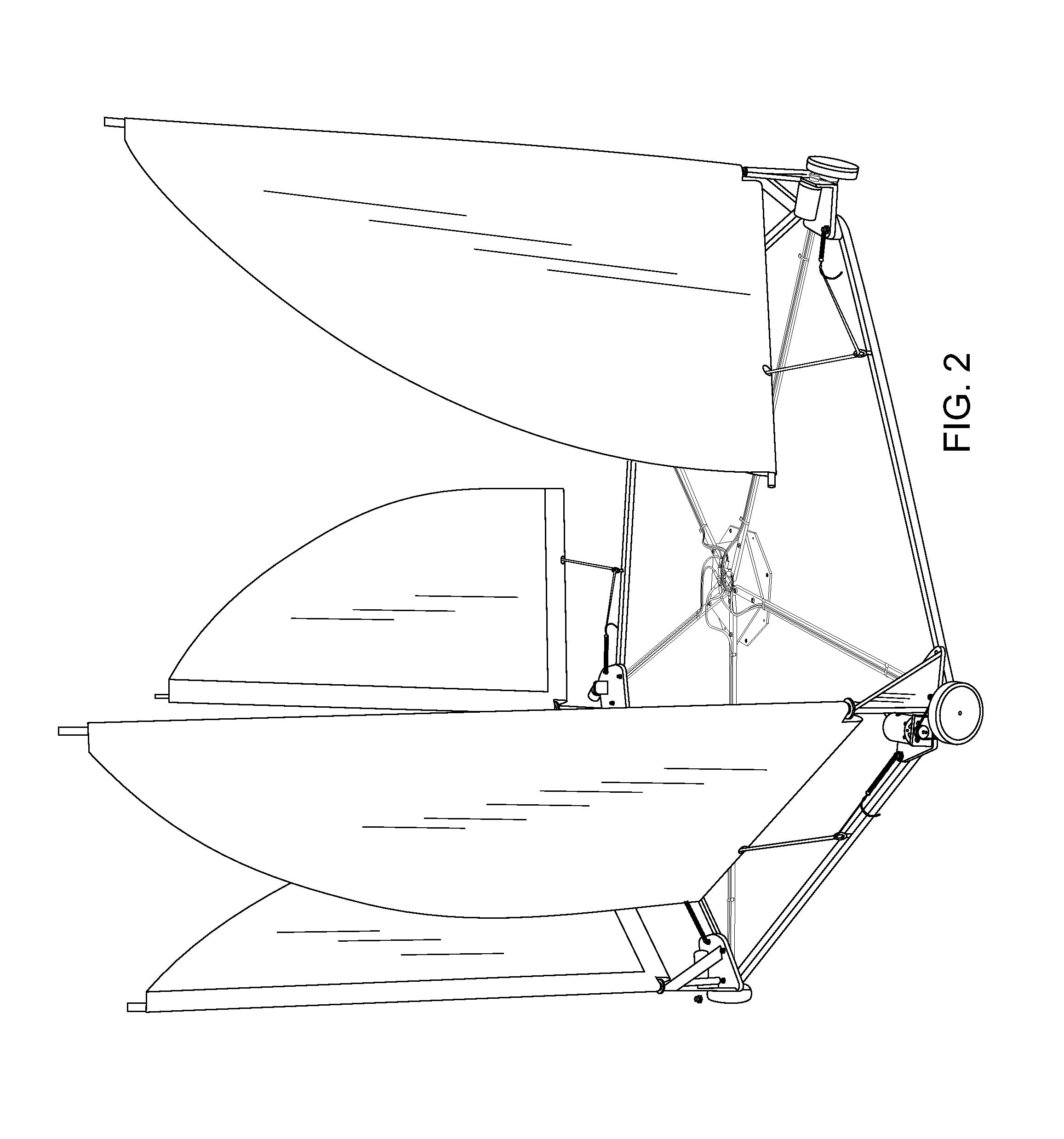
[0091]FIG. 2 illustrates a second embodiment in which the sails have a somewhat different configuration. Each sail is constrained by a spring mechanism such that as the sail rotates, the spring mechanism pulls on the sail. The springs in this embodiment are linear springs, although non-linear spring arrangements may be employed.

[0092]The lower plate is secured...


PUM


Abstract

A system for converting wind power to electrical energy has a peripheral frame, sails interconnected to the peripheral frame, radial struts extending from the hub to the peripheral frame, wheels mounted on the peripheral frame, electric generators interconnected with respective wheels, and a hub about which the peripheral frame is rotatable. The hub is in electrical communication with the electric generators. Sails may be interconnected with the peripheral frame on respective masts, each mast having a base and the mast being pivotable about the base. The electric generators may be mounted on a variety of locations, such as the peripheral frame. Each electric generator may be interconnected with a respective wheel via a belt, a chain or other mechanism. The system may include arrangements to generate electricity from sunlight.

Description

RELATED PATENT APPLICATIONS[0001]This patent application claims the benefit of U.S. Provisional Patent Application No. 61 / 335,376, which was filed on Jan. 6, 2010 and is entitled, “Sail Carousel Wind Turbine,” and which is incorporated by reference herein.BACKGROUND OF THE INVENTION[0002]With a growing need for sources of alternative energy, many efforts have been made to harvest wind power for electrical energy. Currently, wind power is most often harvested by constructing large numbers of windmills or other devices in a complex. The devices tend to be heavy, are prone to breaking down, and are fixed into place at a set location. Repair and maintenance of a windmill, for example, is often dangerous, as it is carried out many feet above the ground, and the cost of operating the complex can be very high.[0003]There are many applications in which it would be useful to have a portable device for generating wind power, that could be lightweight, could be set up on a variety of surfaces,...

Claims


Application Information

Patent Timeline
Patent Type & Authority Applications(United States)
IPC IPC(8): F03D3/02
CPCF03D3/005F05B2240/311Y02E10/74Y02B10/30F05B2240/312Y02B10/70
Inventor KING, WILLIAM L.POPAT, GHANSHYAM
Owner IQ ENERGY
Why Eureka
Try Eureka