Three-dimensional measurement apparatus and control method therefor
a three-dimensional measurement and control method technology, applied in the field of three-dimensional measurement apparatus, can solve problems such as three-dimensional measurement failures
- Summary
- Abstract
- Description
- Claims
- Application Information
AI Technical Summary
Problems solved by technology
Method used
Image
Examples
first embodiment
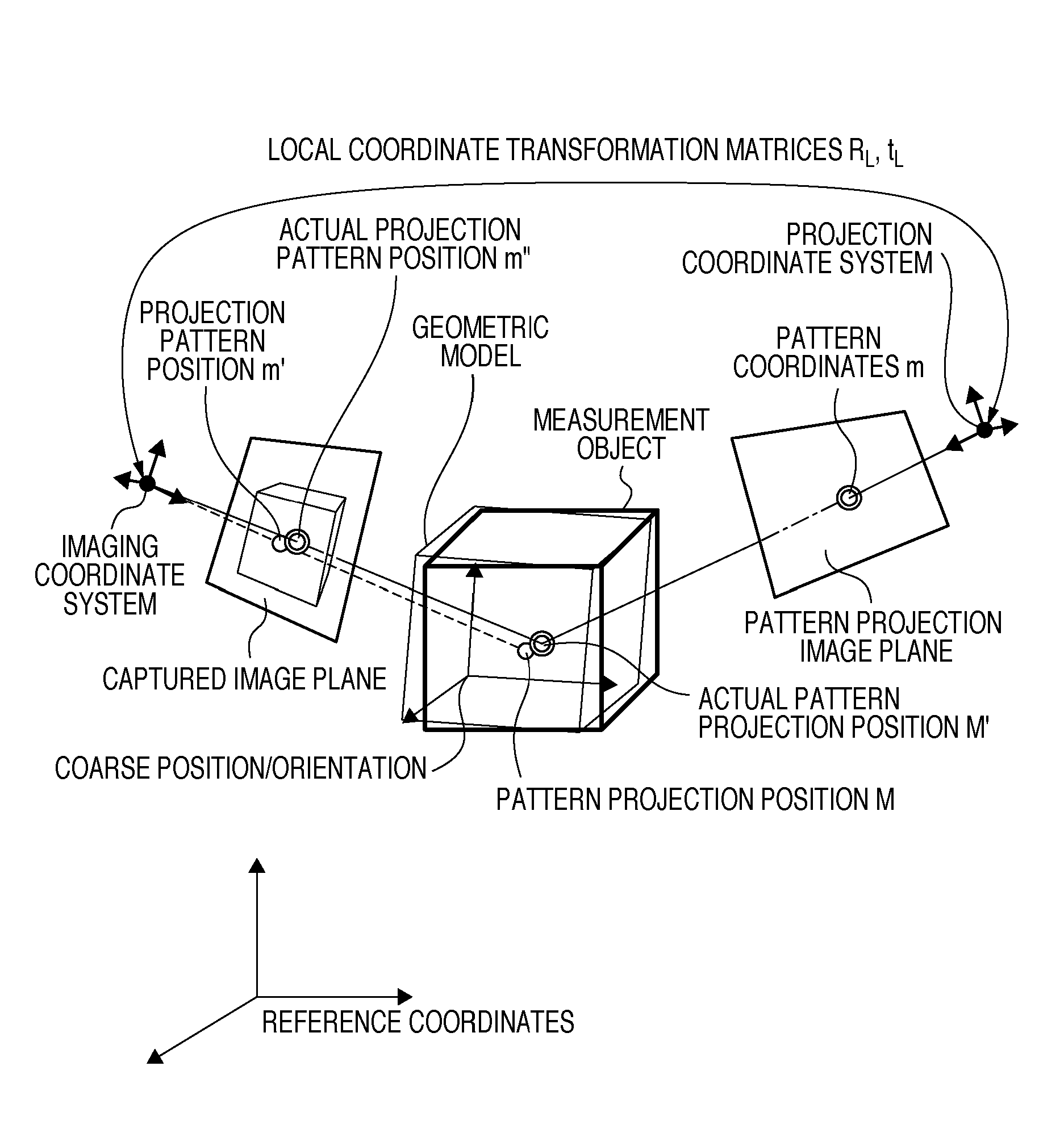
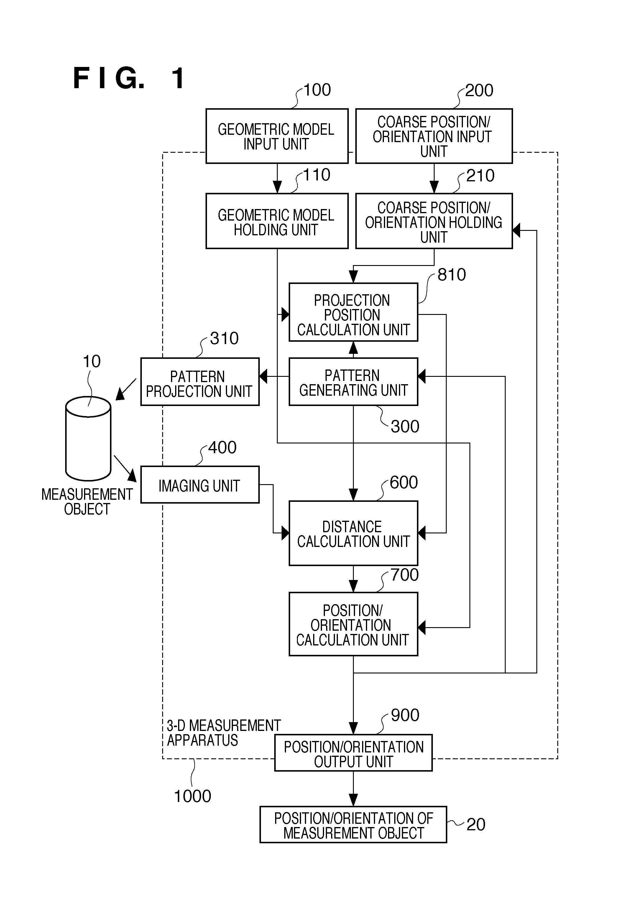
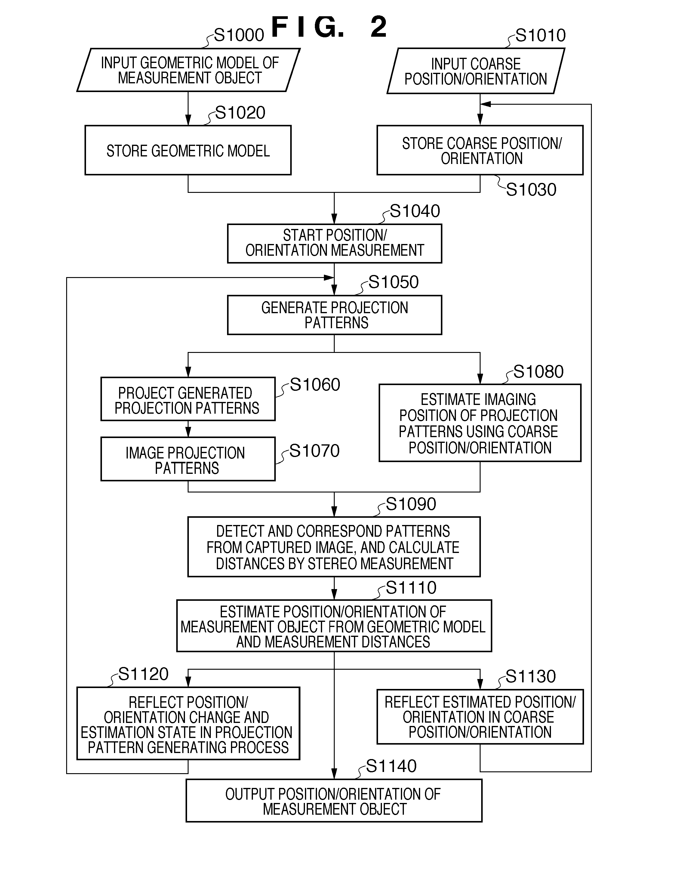
[0023]FIG. 1 is a block diagram of a three-dimensional measurement apparatus according to one embodiment of the present invention. The flow of processing relating to FIG. 1 is shown in FIG. 2. The processing units of the three-dimensional measurement apparatus 1000 will now be described using these diagrams. Note that in the example of the three-dimensional measurement apparatus according to the present embodiment, inputs include a geometric model of the measurement object, an image captured of the measurement object and the coarse position and orientation of the measurement object, and an estimated position and orientation result is output.
[0024]In S1000, a geometric model input unit 100 inputs model information on a measurement object 10 constituting a three-dimensional shape. Model information may be input using a configuration in which information is read out from a recording apparatus or a recording medium such as a floppy (registered trademark) disk, CD-ROM, memory card, hard ...
second embodiment
[0078]As for a suitable application example of the three-dimensional measurement apparatus 1000 described in the First Embodiment, an example is given in which the apparatus is installed on the end effector of an industrial robot arm, and used for the purpose of measuring the position and orientation of an object to be gripped serving as a measurement object. Hereinafter, this application example of the three-dimensional measurement apparatus 1000 will be described using FIG. 8.
[0079]An industrial robot arm 30 is driven under the control of a robot controller 40. The three-dimensional measurement apparatus 1000 serving as one embodiment of the present invention is fixed by a jig to an arm portion. The operation of the industrial robot arm 30 involves picking up an object 11 using a gripper. The three-dimensional measurement apparatus 1000 is connected by a cable in order to sequentially estimate the relative position and orientation of the gripper and the object 11, and convey the e...
third embodiment
[0083]With the present invention, even in the case where the geometric model of the measurement object is unknown, the three-dimensional shape of the measurement object can basically be acquired using an apparatus configuration according to one embodiment of the present invention. The applicable range of the present invention can be further broadened by adding a procedure for acquiring an unknown geometric model of a measurement object, using images from multiple views.
[0084]FIG. 9 is a block diagram showing an example configuration of a three-dimensional measurement apparatus 1010 according to the Third Embodiment. The three-dimensional measurement apparatus 1010 is constituted by adding a measurement model generation unit 120 to the configuration of the three-dimensional measurement apparatus 1000 of the First Embodiment. The measurement model generation unit 120 exhibits the function thereof when the present apparatus is applied to a model having no geometric model. Hereinafter, ...
PUM
 Abstract
Description
Claims
Application Information
 - R&D
- Intellectual Property
- Life Sciences
- Materials
- Tech Scout
- Unparalleled Data Quality
- Higher Quality Content
- 60% Fewer Hallucinations
Browse by: Latest US Patents, China's latest patents, Technical Efficacy Thesaurus, Application Domain, Technology Topic, Popular Technical Reports.
© 2025 PatSnap. All rights reserved.Legal|Privacy policy|Modern Slavery Act Transparency Statement|Sitemap|About US| Contact US: help@patsnap.com


