
Imaging apparatus

a technology of imaging apparatus and spherical tube, which is applied in the direction of color television details, television system details, television systems, etc., can solve problems such as difficulty in setting a desirable ratio

Inactive Publication Date: 2011-07-07
NIKON CORP
View PDF8 Cites 15 Cited by
  • Summary
  • Abstract
  • Description
  • Claims
  • Application Information

AI Technical Summary

Benefits of technology

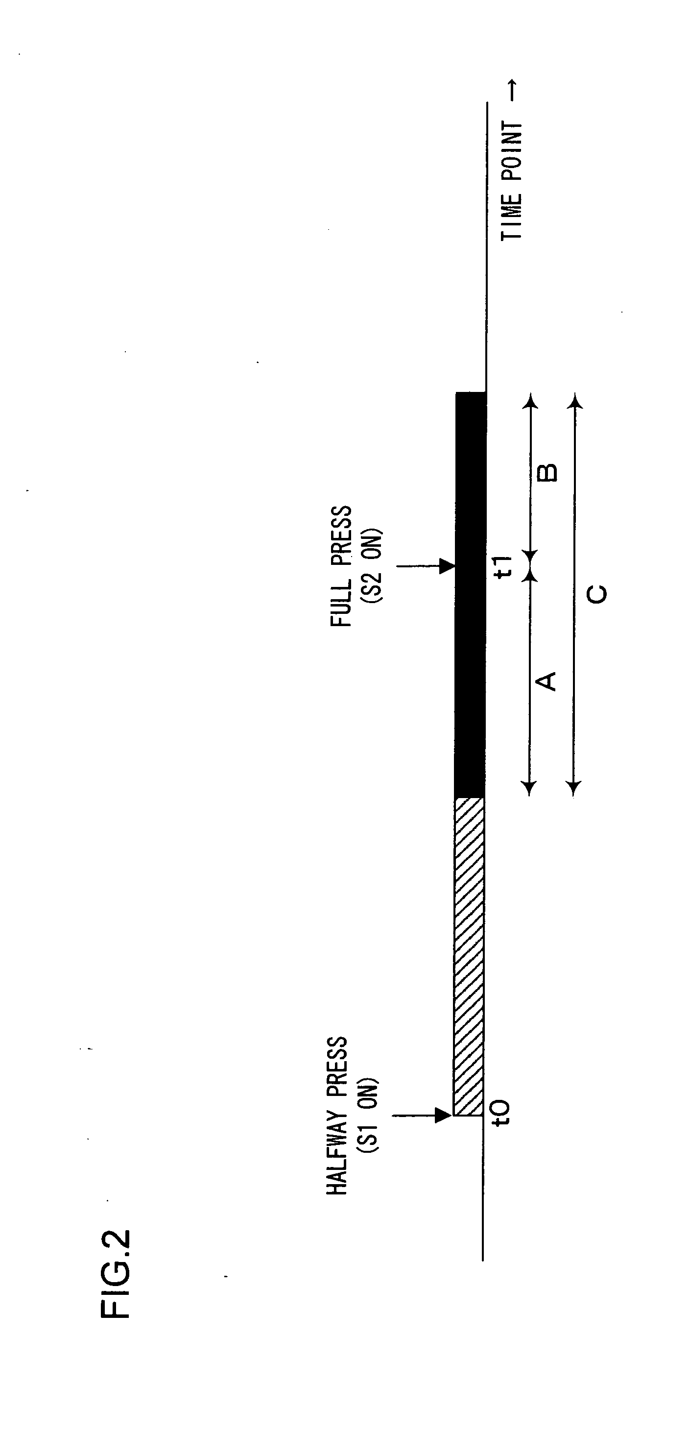
[0014]According to the 6th aspect of the present invention, the candidate number determining unit of an imaging apparatus according to the 5th aspect may increase the candidate number so as to assume a greater value as the sum of A and B in correspondence to a greater extent of the frame-to-frame subject displacement.
[0016]According to the 8th aspect of the present invention, the candidate number determining unit of an imaging apparatus according to the 5th aspect may reduce the candidate number so as to assume an even smaller value as the sum of A and B in correspondence to a smaller extent of the frame-to-frame subject displacement, when a remaining capacity available at the storage unit is equal to or less than a predetermined value.
[0022]The imaging apparatus according to the present invention makes it possible to set optimal values for the number of frame images that are to be obtained before an issue of a photographing instruction signal and the number of frame images that are to be obtained after the issue of the photographing instruction signal.

Problems solved by technology

However, a photographer, not knowing optimal values, may find it difficult to set a desirable ratio.

Method used


Image

  • Imaging apparatus
  • Imaging apparatus
  • Imaging apparatus

Examples


first embodiment

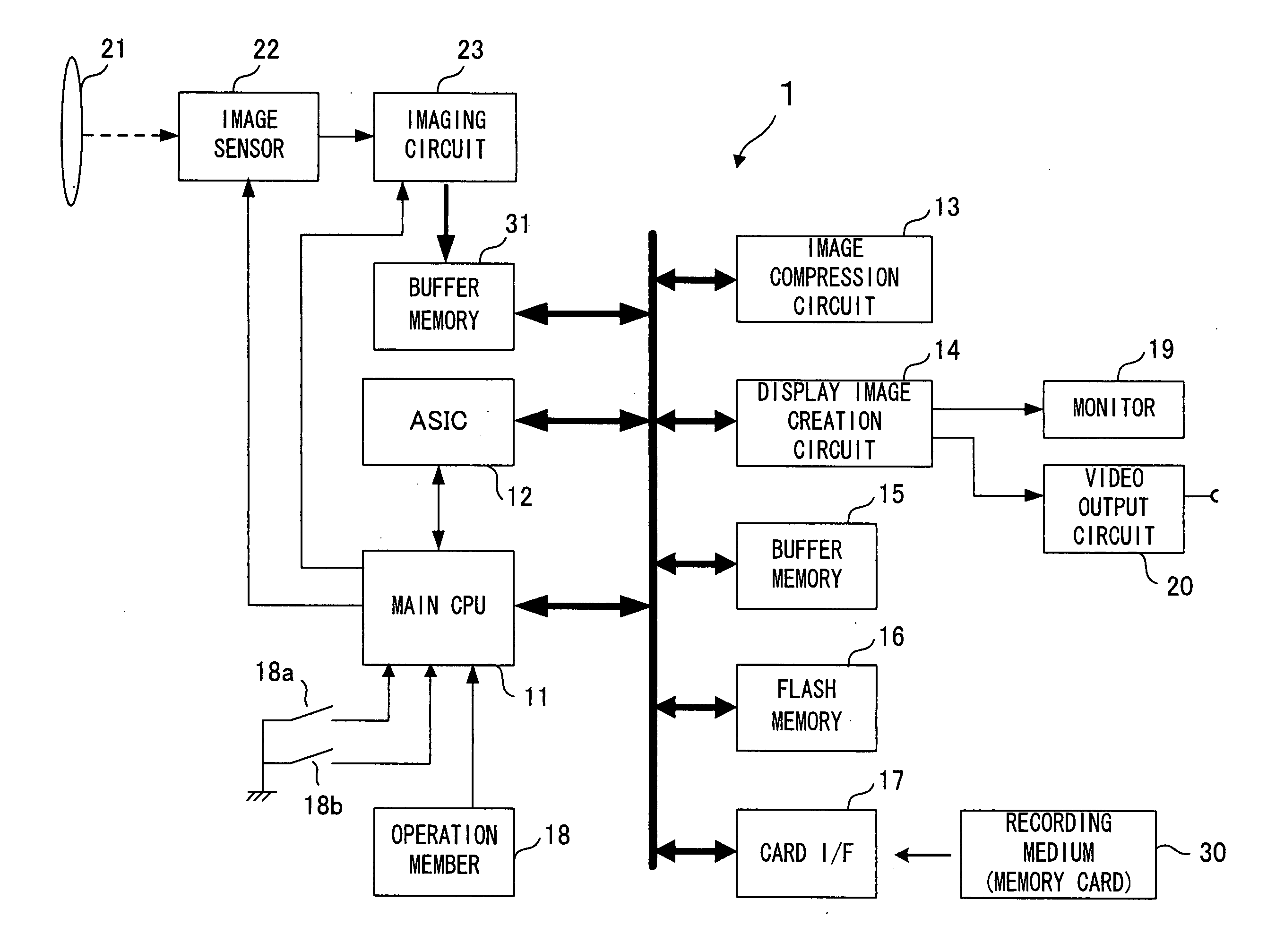
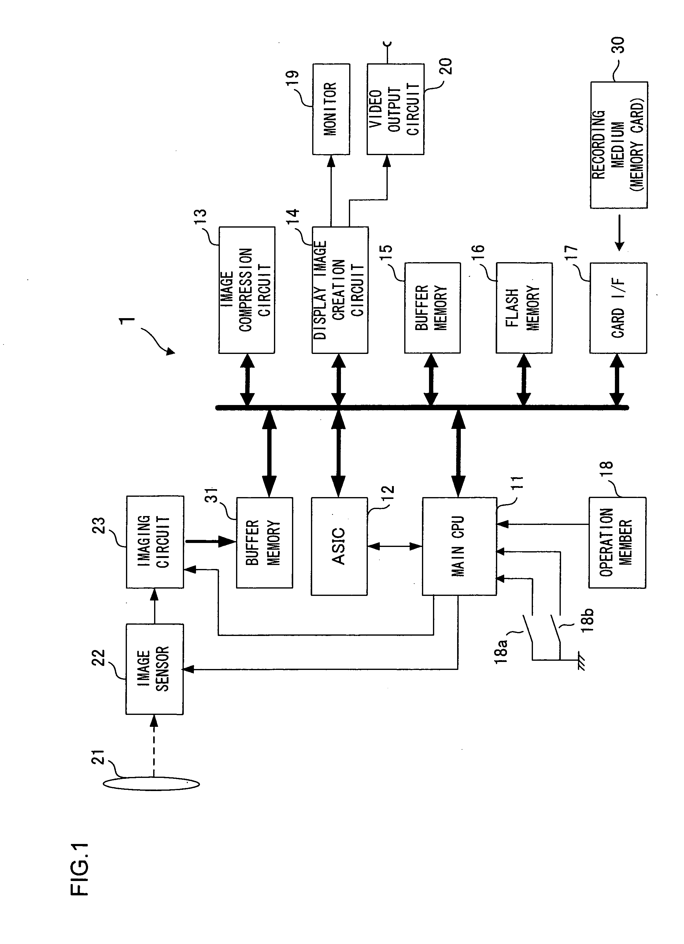
[0032]FIG. 1 is a block diagram showing the essential components constituting an electronic camera 1 achieved in the embodiment of the present tension. The electronic camera 1 is controlled by a main CPU 11.

[0033]A subject image is formed through a photographic lens 21 onto an image-capturing surface of an image sensor 22. The image sensor 22, which may be constituted with a CCD image sensor or a CMOS image sensor, outputs imaging signals obtained by capturing the subject image formed on the image-capturing surface, to an image-capturing circuit 23. The image-capturing circuit 23 executes analog processing (such as gain control) on the photoelectric conversion signals output from the image sensor 22 and also converts the analog image-capturing signals to digital data at a built-in A / D conversion circuit.

[0034]The main CPU 11 executes predetermined arithmetic operations by using signals input thereto from various blocks and outputs control signals, which are generated based upon the ...

second embodiment

[0082]The initial value C is reevaluated in the second embodiment based upon the time difference Δt between the time point at which the frame image selected in step S8 (see FIG. 3) was obtained and the time point at which the full press operation signal originating from the full press switch 18b was input. In reference to the flowchart presented in FIG. 5, the flow of the initial value learning processing executed by the main CPU 11 in the second embodiment is described. The processing in FIG. 5 is executed in place of the processing executed in the first embodiment, as shown in FIG. 4.

[0083]In step S101 in FIG. 5, the main CPU 11 calculates Δt (the difference between the time point at which the selected frame was obtained and the time point at which the full press operation signal was received), and then the operation proceeds to step S102. In step S102, the main CPU 11 stores Δt into the flash memory 16, before proceeding to step S103.

[0084]In step S103, the main CPU 11 executes s...

third embodiment

[0090]In reference to the third embodiment, an arithmetic operation executed to calculate a new C value when the electronic camera is in a focus-locked state is described. In the focus-locked state, the camera is held (locked) in a condition in which it is pre-focused on a subject present over a specific distance from the camera. In the third embodiment, the main CPU 11 accepts a full press operation (in step S4 in FIG. 3) in the focus-locked state.

[0091]Unless the electronic camera is in the focus-locked state, the main CPU 11 will normally adjust focus by driving the focusing lens immediately before starting the shutter release processing in step S5 (see FIG. 3). The CPU 11 in the electronic camera in the focus-locked state, on the other hand, executes the shutter release processing in step S5 (see FIG. 3) while holding (locking) the camera in the focused state.

[0092]Accordingly, the main CPU 11 in the third embodiment calculates the C value to be set as the initial value in step ...


PUM


Abstract

An imaging apparatus includes: an instruction unit that issues a photographing instruction signal; an image sensor that obtains frame images over predetermined time intervals; a storage unit in which a plurality of the frame images obtained via the image sensor are sequentially stored; a save candidate determining unit that designates, among the plurality of the frame images stored in the storage unit, a plurality of the frame images obtained before and after an issue of the photographing instruction signal as candidates of images to be saved into a recording medium; and a candidate number determining unit that automatically determines, based upon specific information, a candidate number of the frame images that are to be designated as candidates by the save candidate determining unit.

Description

INCORPORATION BY REFERENCE[0001]The disclosures of the following priority applications are herein incorporated by reference:[0002]Japanese Patent Application No. 2009-230303 filed Oct. 2, 2009[0003]Japanese Patent Application No. 2010-210983 filed Sep. 21, 2010BACKGROUND OF THE INVENTION[0004]1. Field of the Invention[0005]The present invention relates to an imaging apparatus.[0006]2. Description of Related Art[0007]Japanese Laid Open Patent Publication No. 2001-257976 discloses the following camera. Images photographed over predetermined time intervals following a first shutter release are sequentially stored into a buffer memory and, in response to a second shutter release, images in pre-frames having been photographed prior to the second shutter release (photographing instruction signal), an image in the frame corresponding to the second shutter release (photographing instruction signal) and images in post-frame photographed following the second shutter release (photographing ins...

Claims


Application Information

Patent Timeline
Patent Type & Authority Applications(United States)
IPC IPC(8): H04N5/76
CPCH04N5/232H04N5/23254H04N5/23245H04N23/64H04N23/667H04N23/6811
Inventor TAKAHASHI, AKIHIKOSATO, SHIGEMASA
Owner NIKON CORP
Learn More