Method and apparatus for modulating light

a light modulation and light technology, applied in non-linear optics, instruments, optics, etc., can solve the problem of difficult to achieve pure phase modulation without, and achieve the effect of reducing the number of optical surfaces, low optical losses, and low cos

Inactive Publication Date: 2011-07-07
UNIV OF FLORIDA RES FOUNDATION INC
View PDF6 Cites 10 Cited by
  • Summary
  • Abstract
  • Description
  • Claims
  • Application Information

AI Technical Summary

Benefits of technology

[0005]Embodiments of the invention can utilize multiple pairs of electrodes sequentially positioned on a single modulator crystal, as shown in FIG. 2. Embodiments utilizing multiple electrode pairs on a single modulator crystal can reduce the number of optical surfaces per modulation frequency when multiple modulation frequencies need to be applied to a light field. In applications where low optical losses are important, keeping the number of optical surfaces low can reduce the overall losses.

Problems solved by technology

The generation of amplitude modulation, when certain orientations of the polarization state of the incident light and the orientation of the crystal occur, makes it hard to achieve pure phase modulation without spurious, unwanted, amplitude modulation or polarization rotation.

Method used


Image

  • Method and apparatus for modulating light
  • Method and apparatus for modulating light
  • Method and apparatus for modulating light

Examples


Embodiment Construction

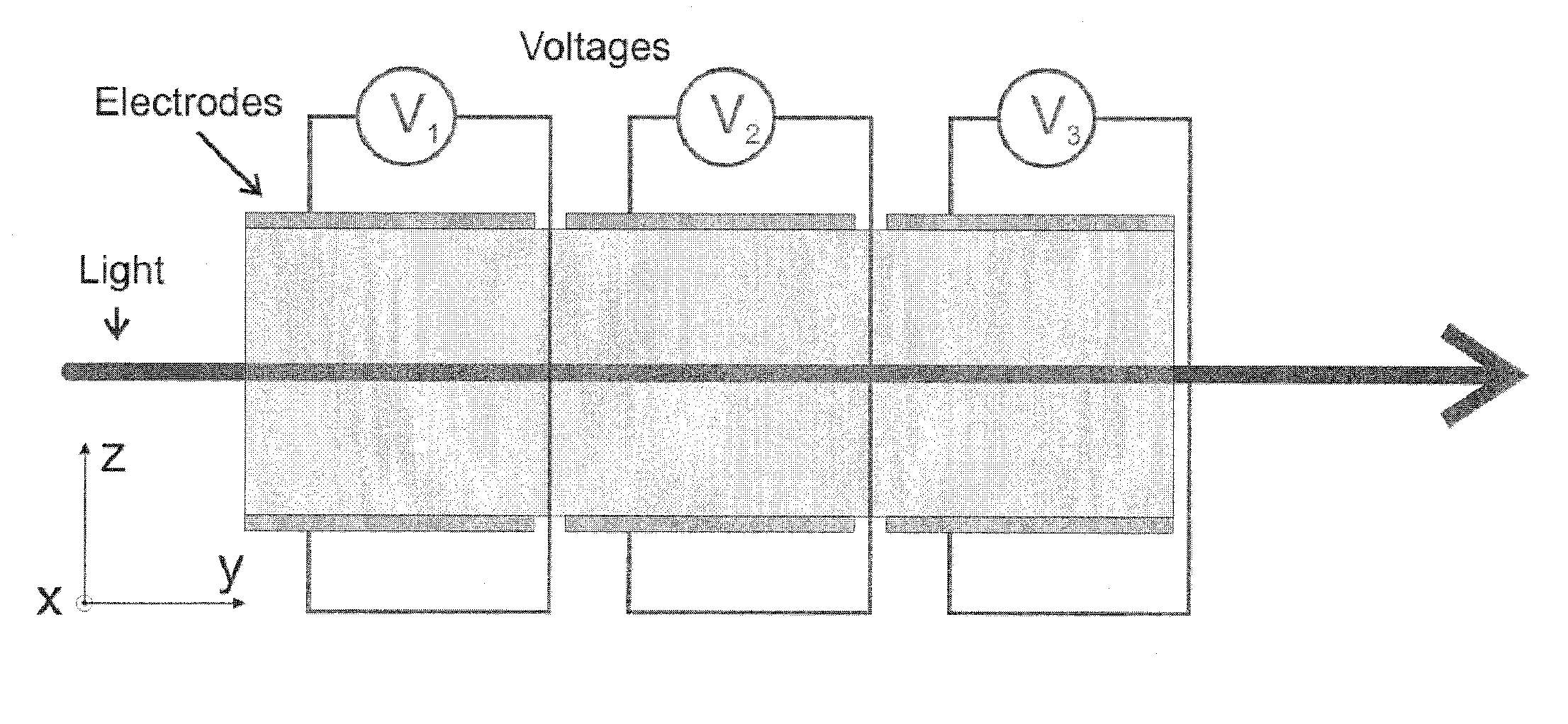
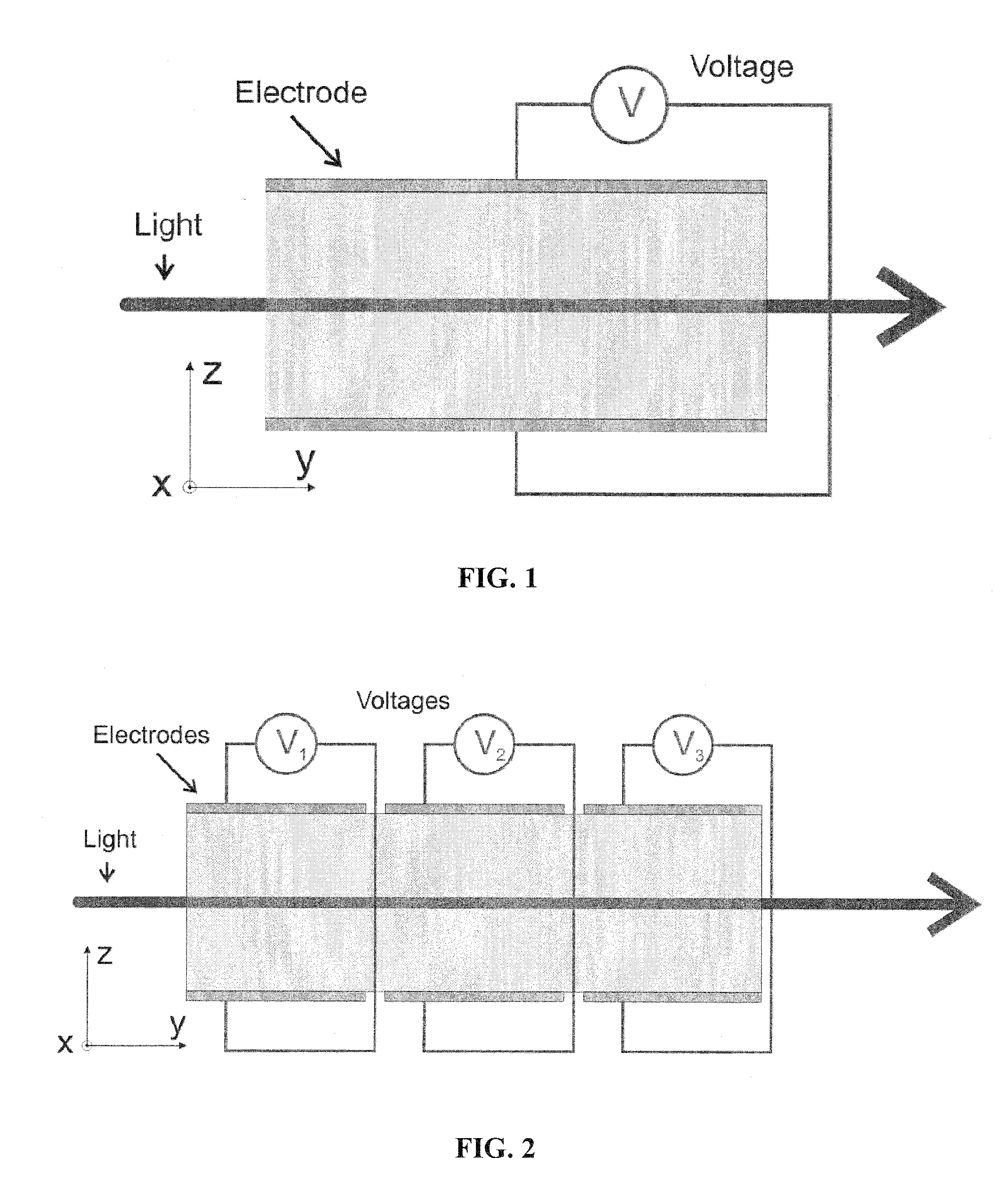
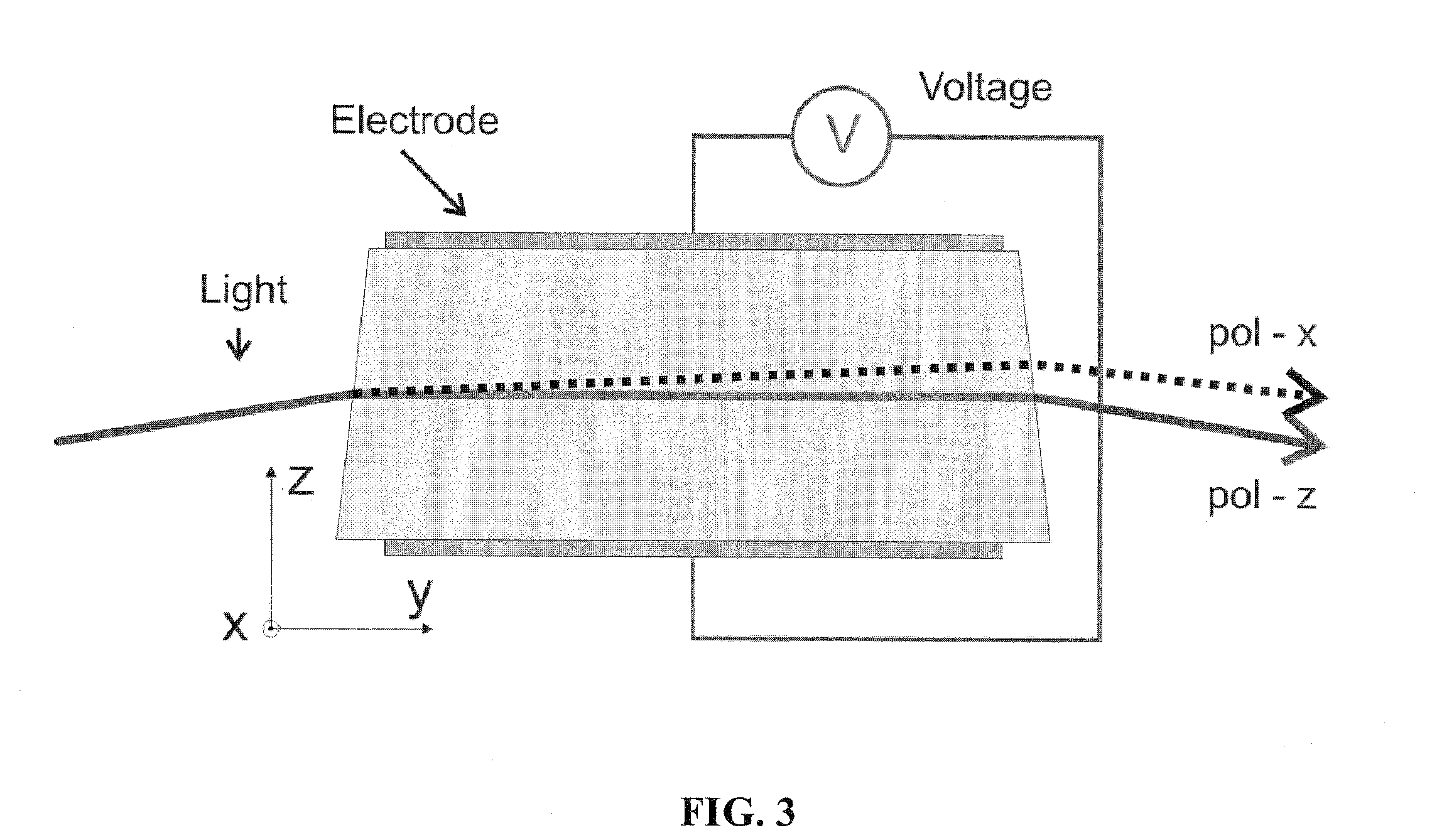
[0011]Embodiments pertain to a method and apparatus for modulating light. The apparatus incorporates a modulator crystal having a electro-optic material. The modulator crystal has an optic axis, a first polarization axis, and a second polarization axis, where the first polarization axis and the second polarization axis are each perpendicular to the optic axis and perpendicular to each other. The device also has at least two electrode pairs, where each electrode pair is positioned such that when a voltage is applied across the electrode pair an electric field is created through a portion of the modulation crystal. The electric field has at least a component perpendicular to the optic axis that modulates the light. The application of the electric field modulates light passing through the modulator crystal that has a direction of travel that has a component parallel to the optic axis. Preferably, the light travels along the optic axis. In specific embodiments, the electro-optic materia...


PUM

PropertyMeasurementUnit
angleaaaaaaaaaa
wedge angleaaaaaaaaaa
reflectivityaaaaaaaaaa

Abstract

Embodiments relate to a method and apparatus for producing polarized light, having a modulator crystal, where the modulator crystal incorporates a birefringent electro-optic material. The modulator crystal has an optic axis, a first polarization axis, and a second polarization axis, where the first polarization axis and second polarization axis are each perpendicular to the optic axis and perpendicular to each other. The apparatus can also include an electrode pair, where application of an electric field modulates light passing through the modulator crystal that is polarized along the first polarization axis. Embodiments pertain to a method and apparatus for modulating light. The apparatus incorporates a modulator crystal having a electro-optic material. The device also has at least two electrode pairs, where each electrode pair that modulates light passing through the modulator crystal that has a direction of travel that has a component parallel to the optic axis.

Description

CROSS-REFERENCE TO RELATED APPLICATION[0001]The present application claims the benefit of U.S. Provisional Application Ser. No. 61 / 080,129, filed Jul. 11, 2008, which is hereby incorporated by reference herein in its entirety, including any figures, tables, or drawings.[0002]The subject invention was made with government support under a research project supported by the National Science Foundation, Contract Numbers PHY-0555453 and PHY-0244902.BACKGROUND OF INVENTION[0003]Phase and amplitude modulation of light is usually generated by the electro-optic effect, where the index of refraction of a dielectric material is changed by applying a variable external electric field. Typically, a sinusoidal electric field with a fixed frequency is applied across a birefringent electro-optic crystal. This effect can be used to generate phase modulation, amplitude modulation, and / or polarization rotation / variation depending on the polarization state of the incident light and the orientation of the...

Claims


Application Information

Patent Timeline
Patent Type & Authority Applications(United States)
IPC IPC(8): G02F1/03
CPCG02F1/0316G02F1/03
Inventor QUETSCHKE, VOLKER M.WU, WANWILLIAMS, LUKEARAIN, MUZAMMIL A.MARTIN, RODICAREITZE, DAVIDTANNER, DAVID B.MUELLER, GUIDO
Owner UNIV OF FLORIDA RES FOUNDATION INC
Why Eureka
Try Eureka