Paper feed device and image formation apparatus using the same

a technology of paper feed and image formation apparatus, which is applied in the direction of electrographic process, instruments, transportation and packaging, etc., can solve the problems of springs stopping working in this state and creating torsion deformation, so as to reduce the stopping force of the detent of the electromagnetic absorber, shorten the life of the drive transmission unit, and facilitate control

Inactive Publication Date: 2011-07-07
RICOH KK
View PDF8 Cites 4 Cited by
  • Summary
  • Abstract
  • Description
  • Claims
  • Application Information

AI Technical Summary

Benefits of technology

[0014]Since the paper feed device having the above-mentioned structure can utilize the electromagnetic absorber to cause the rotation of the rotation shaft and the rotation of the control unit to stop, the end of the spring on the side of the rotation shaft cannot rotate together with the paper feed roller; that is, it is possible to cause the drive transmission unit to stop in a state where the spring does not receive a load so that shortening of the life duration of the drive transmission unit can be avoided. Furthermore since the rotation of the control unit and the rotation of the rotation shaft do not stop together, i.e. the rotation of the rotation shaft stops after the rotation of the control unit stops, a stopping force of the detent of the electromagnetic absorber is reduced and it is easy to control the relative position between the rotation shaft and the control unit.

Problems solved by technology

At this time, since an end of the spring is fixedly connected to the control unit and another end of the spring is fixedly connected with respect to the rotation shaft, in a situation where there is no rotation in the control unit and the rotation shaft rotates, an unexpected torsion force may occur in the spring; this unexpected torsion force may cause the spring to create torsion deformation, and may cause the spring to stop working in this state.

Method used


Image

  • Paper feed device and image formation apparatus using the same
  • Paper feed device and image formation apparatus using the same
  • Paper feed device and image formation apparatus using the same

Examples


first embodiment

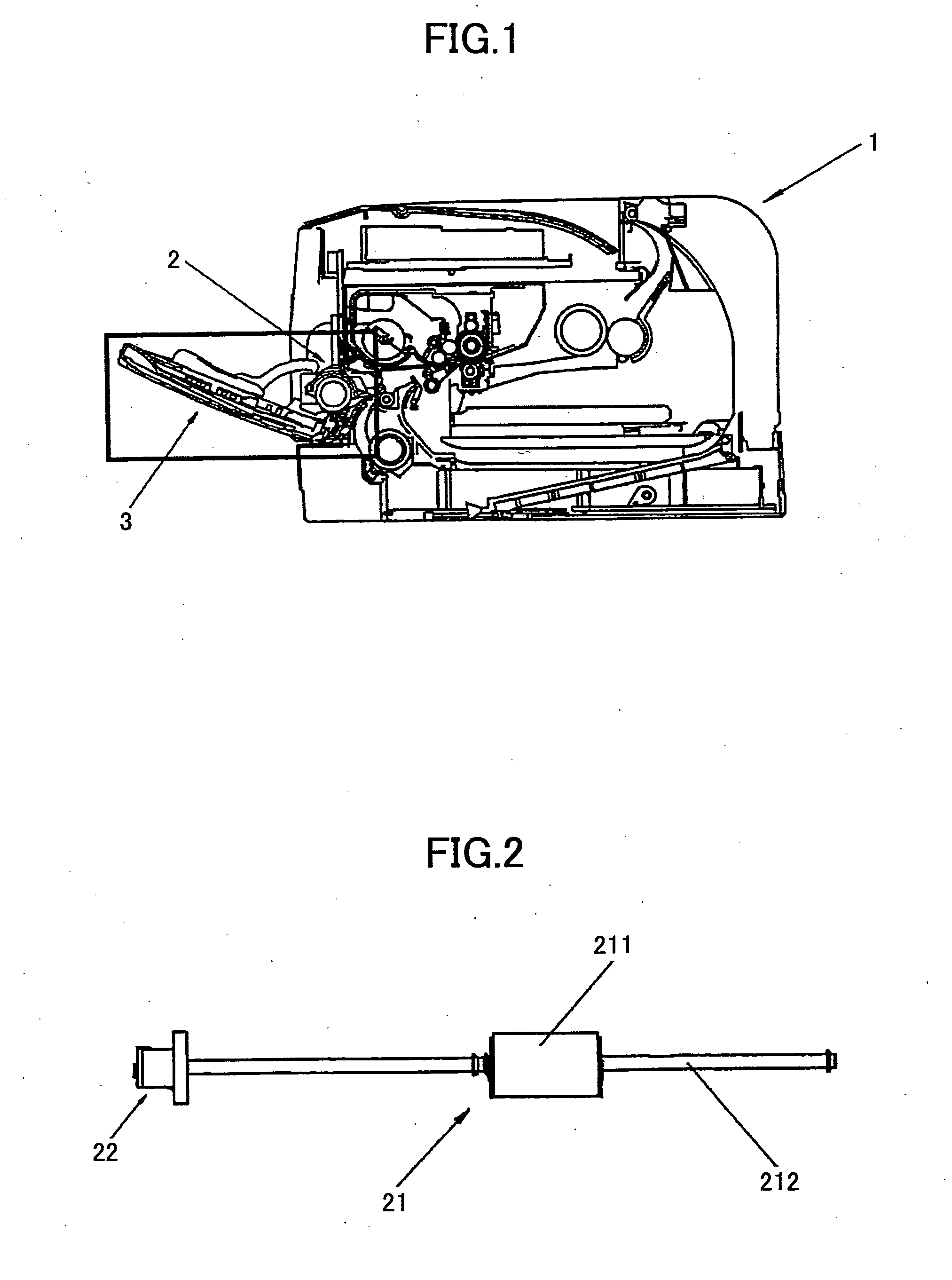
[0024]As shown in FIG. 1, an image formation apparatus 1 according to the present invention comprises a paper feed tray 3 and a paper feed device 2. One or more paper sheets needing to be printed are stacked on the paper feed tray 3, and the paper feed tray 3 is pivotally disposed in an opening on one sidewall of the image formation apparatus 1. When the paper feed tray 3 opens, the opening of the image formation apparatus 1 opens toward the outside. The paper feed device 2 is disposed inside the image formation apparatus 1 and is located near a pivot around which the paper feed tray 3 pivots so that the paper sheets can be transported from the paper feed tray 3 to an imaging unit (not shown in the drawings) inside the image formation apparatus 1.

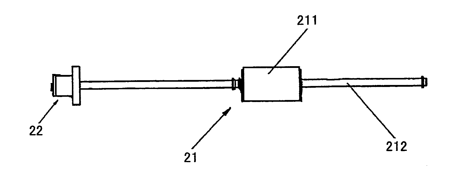
[0025]As shown in FIG. 2, the paper feed device 2 includes a paper transport unit 21; the paper transport unit 21 includes a paper feed roller 211 and a rotation shaft (i.e. a load shaft) 212. The rotation shaft 212 extends along the direct...

second embodiment

[0045]In the present invention, in a situation where the rotation speed of the control unit 2212 and the rotation speed of the rotation shaft 212 are not very fast, a stopping force acting on a control unit stopper 2234 applied by the detent 232 is not very big. In this situation, since the control unit stopper 2234 does not need high strength, it is possible to utilize the structure shown in FIG. 7. In this embodiment, a rotation shaft stopper 2231 is formed at a position that is on the external wall of the part of the rotation shaft drive unit 222 having the maximum external diameter, and is close to the control unit 2212. An control unit stopper 2234 is formed at a position that is on the external wall of the control unit 2212 and is close to the part of the rotation shaft drive unit 222 having the maximum external diameter; also the control unit stopper 2234 axially sticks out toward the part of the rotation shaft drive unit 222 having the maximum external diameter. The control ...


PUM


Abstract

Disclosed are a paper feed device and an image formation apparatus using the same. The device comprises a drive transmission unit disposed on one end of a rotation shaft, including a clutch gear, a control unit, and a spring; a control unit stopper fixedly disposed on the control unit; and an electromagnetic absorber including a detent. When the detent is located at a brake-off position, the detent and the control unit stopper are separated. When the detent is located at a braking position, the detent makes contact with the control unit stopper, and stops the rotation of the control unit.

Description

BACKGROUND OF THE INVENTION[0001]1. Field of the Invention[0002]The present invention relates to a paper feed device, and more particularly relates to a paper feed device used in an image formation apparatus and an image formation apparatus using the paper feed device.[0003]2. Description of the Related Art[0004]In conventional techniques, a paper feed device used in an image formation apparatus usually employs cooperative action jointly undertaken by a mechanical spring clutch and an electromagnetic absorber to control the rotation behavior and the stop behavior of a paper feed roller. In a conventional mechanical spring clutch, a load shaft (i.e. a rotation shaft) of a paper feed roller is connected to a clutch gear by using a spring, and acts (i.e. rotates) according to the rotation transmitted from a drive gear chain in an image formation apparatus to the clutch gear; by controlling, using a control unit stopper controlled by the electromagnetic absorber, whether the rotation of...

Claims


Application Information

Patent Timeline
Patent Type & Authority Applications(United States)
IPC IPC(8): B41J11/42B65H5/00
CPCB65H3/0669B65H2403/723G03G15/6529G03G15/6511B65H2403/724
Inventor LI, GUO
Owner RICOH KK
Why Eureka
Try Eureka