Sight for a firearm

a technology for sighting and firearms, applied in the field of sight, can solve the problems of separating the plastic sight from the anchoring position and affecting the safety of the firearm, and achieve the effect of further increasing the mechanical strength

Inactive Publication Date: 2011-07-14
GLOCK GASTON
View PDF5 Cites 8 Cited by
  • Summary
  • Abstract
  • Description
  • Claims
  • Application Information

AI Technical Summary

Benefits of technology

[0011]It is the object of the invention to provide a sight, or the fastening for a sight, particularly of synthetic material in which the seat as well as the mechanical strength are further increased.
[0012]In accordance with the invention, the objects are met by providing the sight parallel or in alignment with the axis of its base with an internal thread and to tighten or securing the sight by means of a screw which can be screwed in from the interior of the carriage. In this manner, the seat of the sight in the carriage is significantly improved wherein, when suitable screws are used, the necessity for using a tool by changing the sight can be kept low; in this manner, knurled head screws or screws with a hexagonal head, also provided with a slot, are accessible for any type of tool.
[0013]In a further development, the screw protrudes in the mounted state beyond the outer surface of the carriage so as to fill out the body of the sight to the extent possible completely, at least, however, by 60% of the height of the sight. In this manner, the mechanical fastening of the sight is significantly improved because any type of mechanical load, particularly impacts and contacts are transmitted directly from the sight to the metal screw. The sight itself can only be subjected locally to pressure which is a load to which the synthetic material is to a higher degree resistant.

Problems solved by technology

It has now been found that during various applications in extremely rough operation of these plastic sights, these plastic sights are separated from their anchoring positions and can be damaged even though they are of synthetic material having excellent mechanical properties.

Method used


Image

  • Sight for a firearm
  • Sight for a firearm
  • Sight for a firearm

Examples


Embodiment Construction

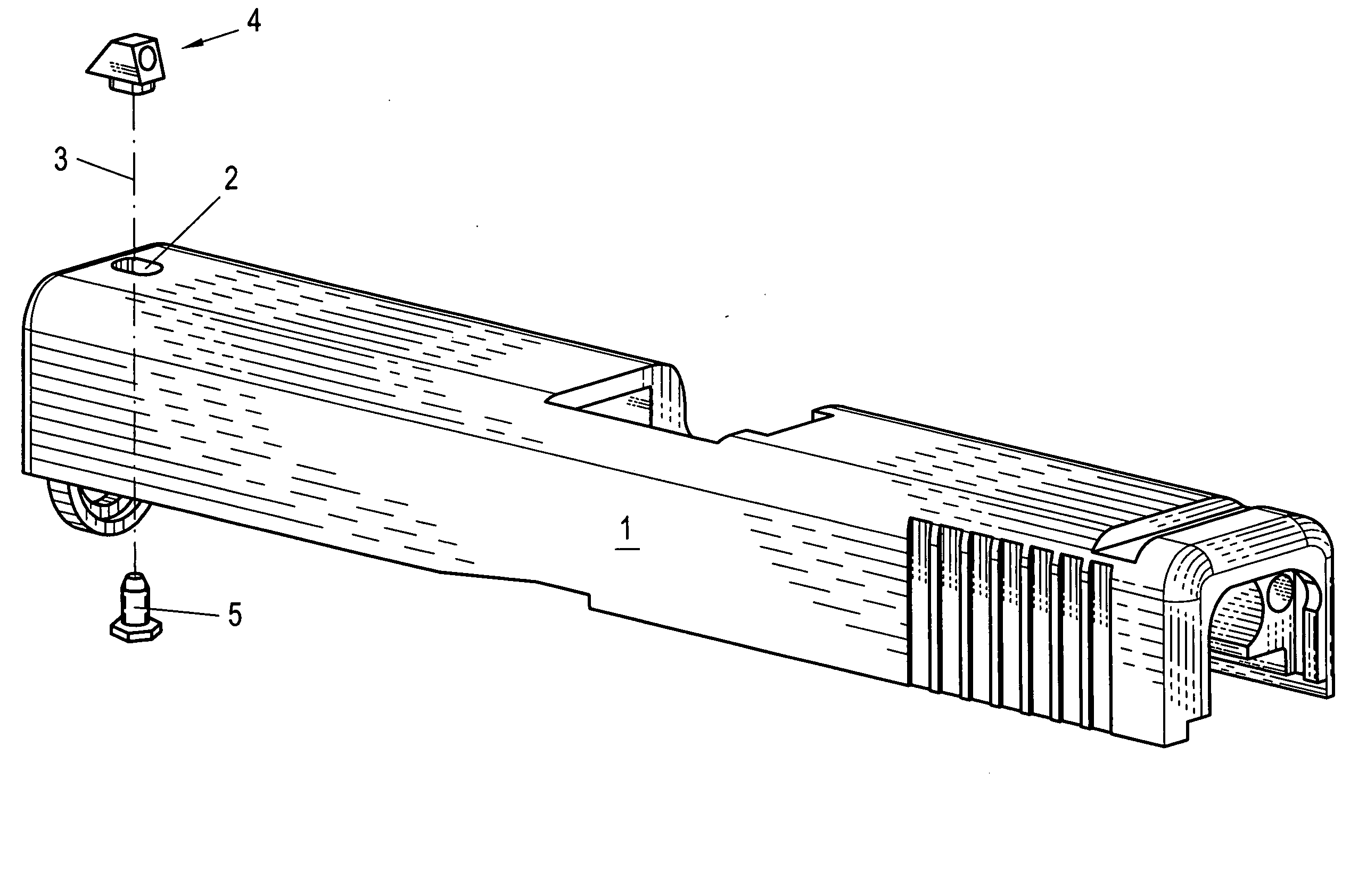
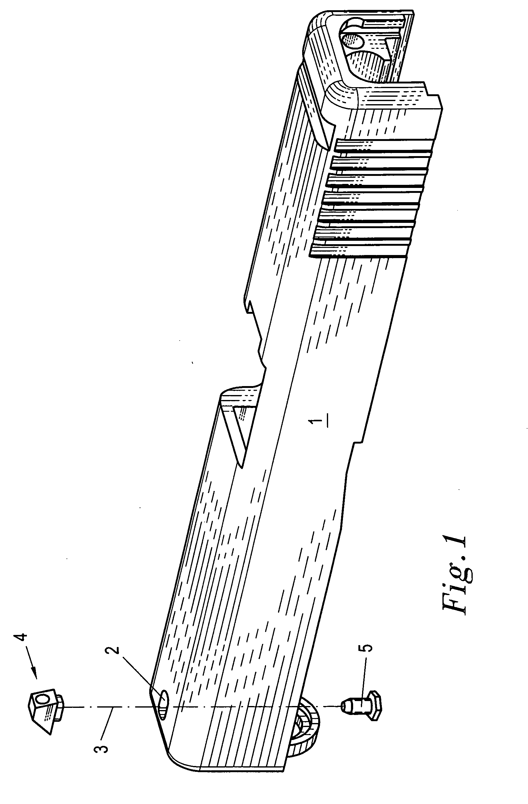
[0019]FIG. 1 shows a carriage 1 of a firearm in whose front region is located a through-opening 2 which is oblong in the cross-section thereof. Along the axis 3 of this opening, displaced upwardly or downwardly in the manner of an explosion, is an inventive sight 4 and a corresponding fastening screw 5.

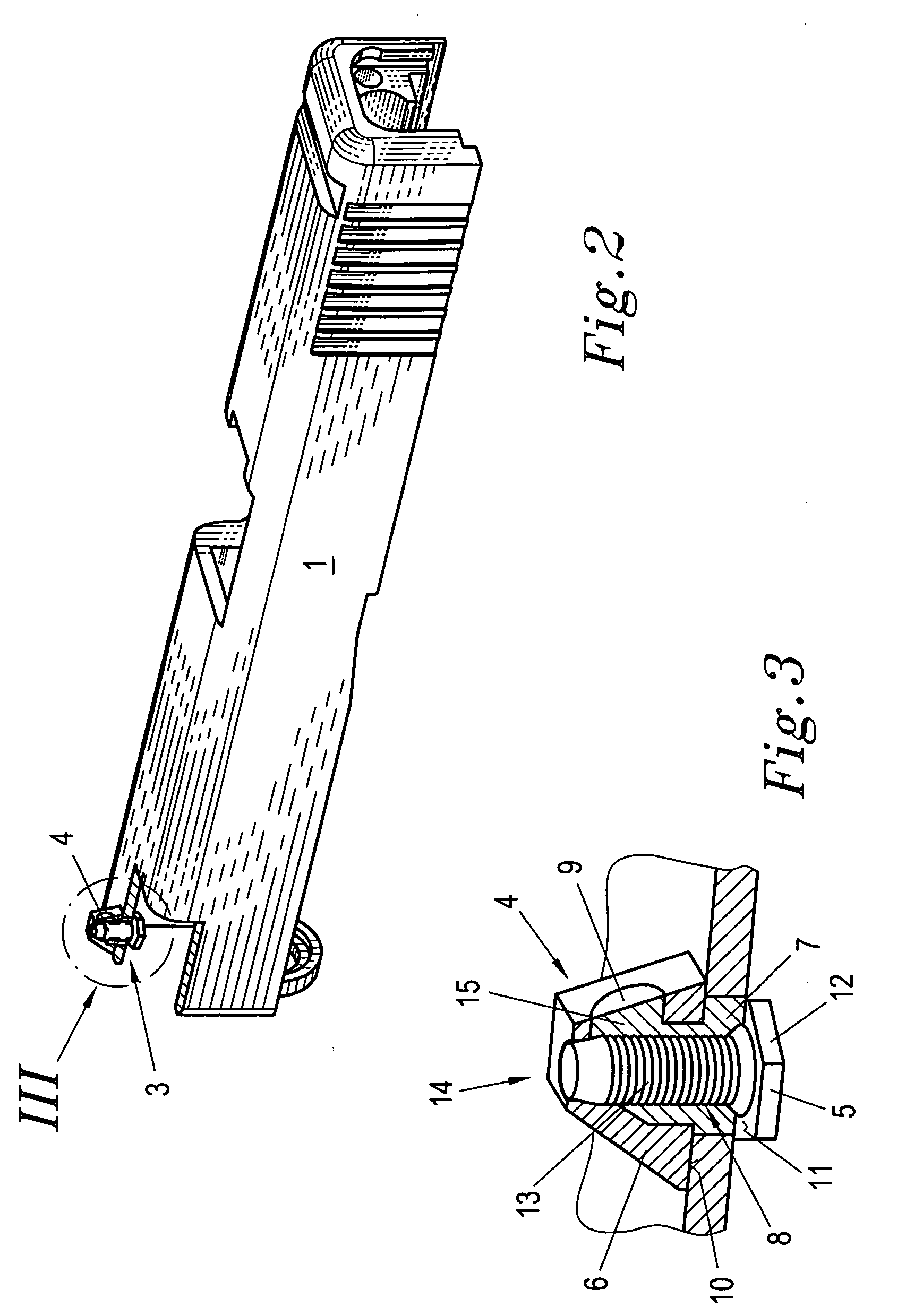
[0020]FIG. 2 shows the assembled state, wherein, for a better illustration, a part of the carriage 1 is broken away.

[0021]FIG. 3 shows detail III on a larger scale. It can be seen that the sight 4 is composed of an inner body 15 and an outer sleeve 6, wherein the inner body forms a leg 7 which can be inserted rapidly and tightly into the through-opening 2. Parallel to the axis 3, preferably in alignment with the axis 3 of the through-opening (FIG. 1), the inner body 15 has at its leg 7 and past the leg 7 an internal thread 8. In the illustrated embodiment, the inner body 15 of the sight 4 also forms a sight point 9 which facilitates aiming with the firearm.

[0022]The screw 5 has an ext...


PUM


Abstract

The invention relates to a sight which is fastened to a structural component of a firearm, preferably the carriage of a pistol. The invention is characterized in that the sight (4) has parallel to or in alignment with the axis of its base an internal thread and is secured by means of a screw (5) which can be screwed in from the interior of the structural component of the firearm. It is preferably provided that in the mounted state the leg (7) of the sight (4) protrudes into a through-opening (2) of the structural component of the firearm.

Description

BACKGROUND OF THE INVENTION[0001]1. Field of the Invention[0002]The invention relates to a sight which is mounted at a carriage or another structural component of a firearm, preferably a pistol.[0003]There are several configurations and types of fastening sights; for example, the sights may be of metal or synthetic material; they can be made of one piece with the carriage or a compatible component, for example; they may be made in one piece with the carriage or the structural component compatible therewith (in the following, the carriage is always referred to only as the carriage because of the easier readability) or are screwed to the carriage or they can also be connected to the carriage through frictional engagement.[0004]For various reasons, sites of synthetic material have been found useful which have a leg by means of which they are inserted into a blind-endhole or through-hole of the carriage and are secured in this position by frictional engagement. These sites are simple an...

Claims


Application Information

Patent Timeline
Patent Type & Authority Applications(United States)
IPC IPC(8): F41G1/00
CPCF41G1/26F41G1/10
Inventor GLOCK, GASTON
Owner GLOCK GASTON
Why Eureka
Try Eureka