Greenhouse

a greenhouse and greenhouse technology, applied in the field of greenhouses, can solve the problems of extremely high energy consumption of greenhouses, poorly suited to our cold conditions, and large expenditure of energy costs, and achieve the effect of saving energy

Active Publication Date: 2011-07-14
MYNTTI ASKO
View PDF10 Cites 15 Cited by
  • Summary
  • Abstract
  • Description
  • Claims
  • Application Information

AI Technical Summary

Benefits of technology

[0023]Inside the greenhouse, light which is not used by the plants for photosynthesis is converted into thermal radiation, and is thus useful. The roof covering, which is opaque, may be provided with solar cells, and energy produced by the solar cells is used e.g. for heating irrigation water or for artificial lighting. The greenhouse is further equipped with a good heat recovery system for ventilation exit air, such energy being used for heating the incoming air and thus yielding major savings in energy.
[0024]In summer, the opaque roof, the insulating material portion of the ceiling and the solar cells prevent the greenhouse from becoming exposed to excessive heat and light during the daytime.

Problems solved by technology

Energy costs represent an extremely large item of expenditure in greenhouse cultivation.
The existing basic models of greenhouses are mainly designed for southern conditions and are thus often poorly suited for our cold conditions.
The energy consumption of greenhouses is extremely high in winter since glass roofs and walls of the greenhouses that receive the smallest amount of sunlight are poorly thermally insulated.
On the other hand, in the summer the problem with the existing greenhouses is that owing to the long days the thermal load tends to become even too heavy.
However, the structural and functional solutions of such elements are not at all usable in the ice and snow conditions of the northern winter.

Method used


Image

  • Greenhouse
  • Greenhouse
  • Greenhouse

Examples


second embodiment

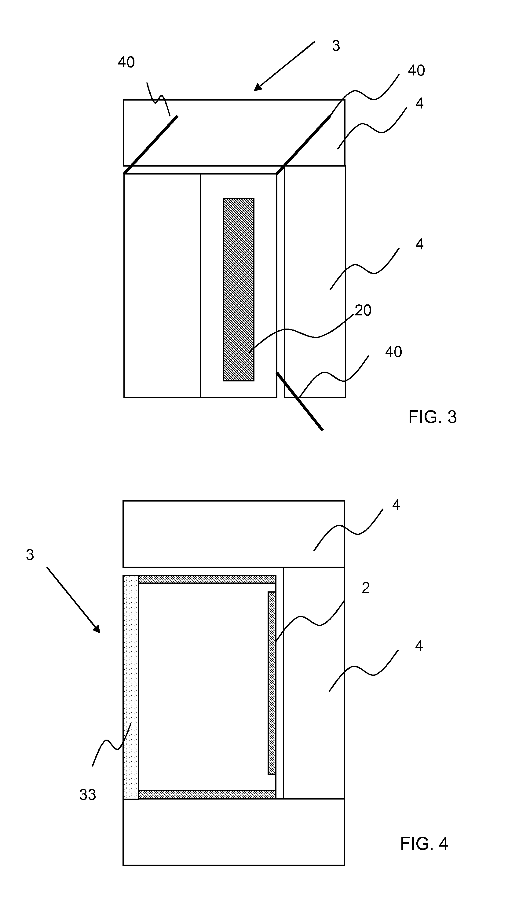
[0059]FIG. 4 shows a horizontal section of the greenhouse 3. As above, the outside walls of the greenhouse are provided with translucent surfaces 2 and an opaque outside wall portion 33. In this embodiment, the translucent surfaces are placed on three sides of the greenhouse abutting on one another. This enables sunlight to be received into the greenhouse from three geographical directions. Light reflecting surfaces 4 are provided in connection with these translucent surfaces as well.

third embodiment

[0060]FIG. 5 shows the greenhouse 3 as seen from above. Translucent surfaces 2 are placed on three sides of the greenhouse, enabling sunlight B to be received into the greenhouse from three geographical directions. Light reflecting surfaces 4 similar to those described above are provided at the front of these translucent surfaces. The greenhouse further comprises vertically positioned light reflecting surface elements 40. This enables the surface area of the sunlight reflecting surfaces to be increased and, also, light coming from the side to be reflected into the greenhouse more efficiently. The vertically positioned light reflecting surface elements 40 are preferably fastened to the outside wall pivotally such that they may be turned to protrude in different directions from the outside wall. In such a case, the amount of light being reflected inside may always be optimized at different times of the day. During the darkest winter months, the surface elements may be directed at the ...


PUM


Abstract

The present invention relates to a greenhouse comprising outside walls provided with translucent surfaces (2) such that light may be received into the greenhouse (3) from at least two geographical directions, a roof structure (7) and a roof (6) provided with an insulating material portion. The invention is characterized in that the outside walls, in connection with the translucent surfaces (2), are provided with a light reflecting yard structure which resides below the translucent surfaces (2), above a ground surface (50), and extending away from the outside wall. The greenhouse (3) may further comprise vertically positioned light reflecting surface elements (40) and light reflecting shade elements (44) movable in a direction parallel with the transparent surfaces (2).

Description

BACKGROUND OF THE INVENTION[0001]The invention relates to a greenhouse according to the preamble of claim 1, which is particularly suited for northern conditions wherein growing requires both artificial light and additional heating.[0002]Energy costs represent an extremely large item of expenditure in greenhouse cultivation. For instance in 2000 to 2006, electricity costs almost doubled and fuel costs increased approximately 40%. Further, energy production utilizes large amounts of fossil fuels for which saving goals relating to environmental protection exist.[0003]The temperature at latitudes north is highly significantly lower than at latitudes south. The existing basic models of greenhouses are mainly designed for southern conditions and are thus often poorly suited for our cold conditions. The energy consumption of greenhouses is extremely high in winter since glass roofs and walls of the greenhouses that receive the smallest amount of sunlight are poorly thermally insulated. On...

Claims


Application Information

Patent Timeline
Patent Type & Authority Applications(United States)
IPC IPC(8): A01G9/14F24S90/00
CPCA01G9/243F24J2/16Y02E10/40F24J2/42Y02B10/20F24J2/18F24S90/00F24S23/79F24S23/77Y02P60/12Y02A40/25A01G9/14F21S11/00
Inventor MYNTTI, ASKO
Owner MYNTTI ASKO
Why Eureka
Try Eureka