

Compact electromechanical actuator
a technology of electromechanical actuators and actuators, applied in the direction of mechanical energy handling, synchronous machines with stationary armatures, rotating magnets, etc., can solve the problems of relatively high weight of electromechanical actuators and inability to be used in conjunction
- Summary
- Abstract
- Description
- Claims
- Application Information
AI Technical Summary
Benefits of technology
Problems solved by technology
Method used
Image

Examples
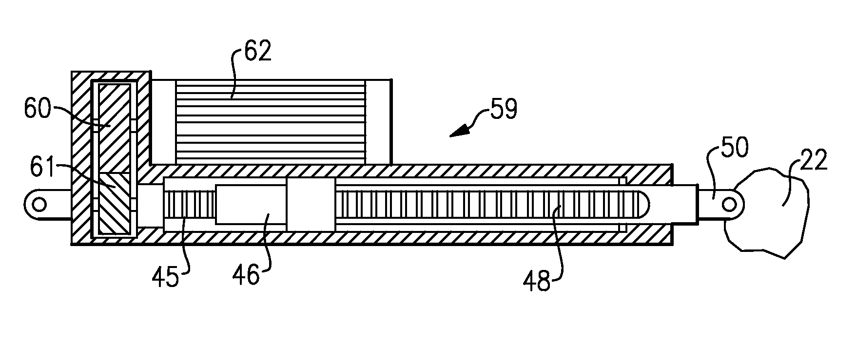
embodiment 59
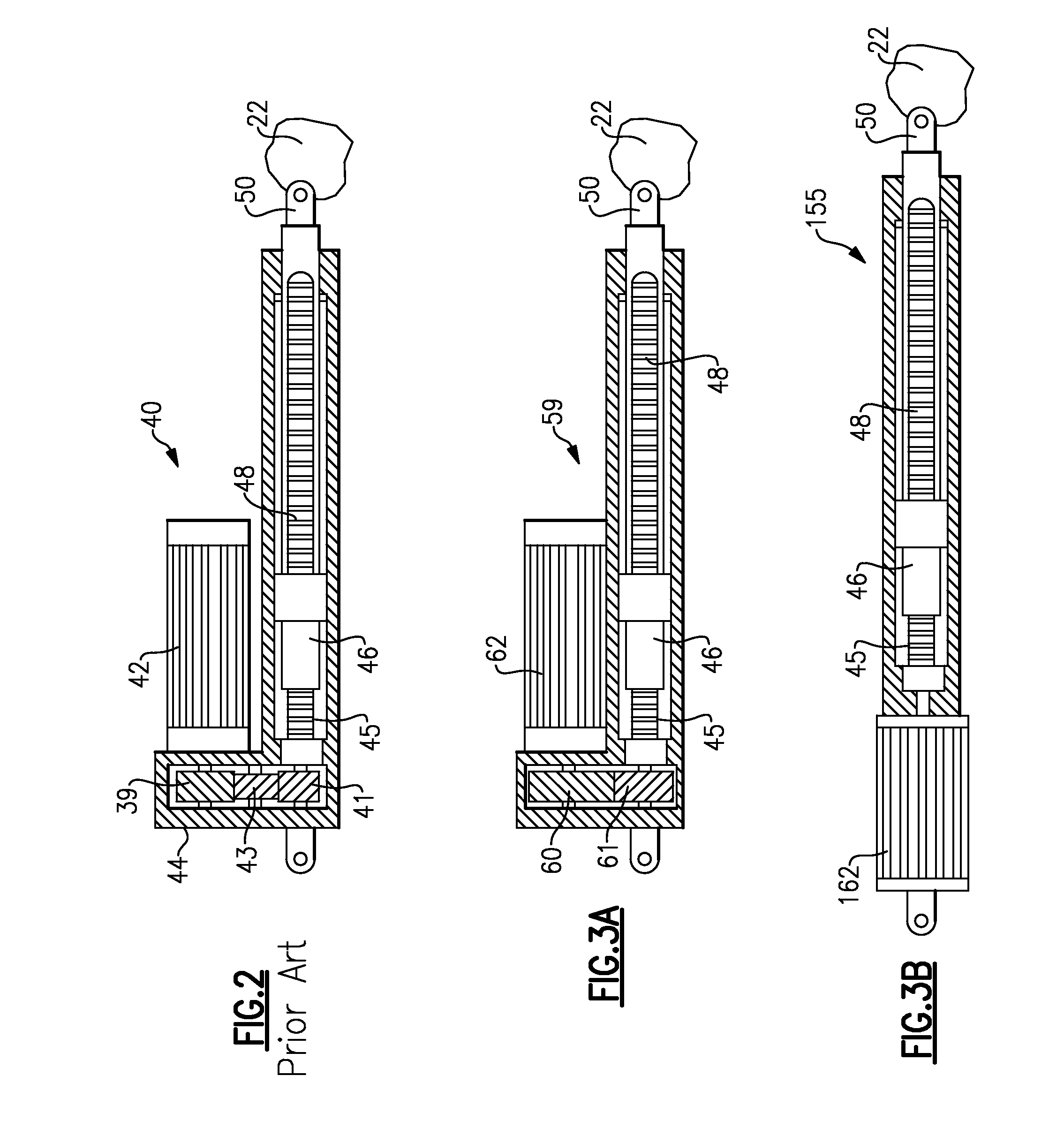
[0023]FIG. 3A shows an inventive embodiment 59 wherein a transverse flux motor 62 is utilized. A transverse flux motor can provide a relatively lower speed because high input frequency is converted electromagnetically into low speed of the shaft. This is an inherent and most important feature of a transverse flux motor. The transverse flux motor 62 drives a first gear 60 which in turn drives a gear 61 to drive the threaded shaft 45. The remainder of the connection may be as known in the prior art.
[0024]FIG. 3B shows an alternative arrangement 155 wherein the transverse flux motor 162 drives the shaft 45 directly.
[0025]As can be appreciated from FIGS. 3A and 3B, a reduction in weight is achieved with these arrangements compared to the prior art of FIG. 2.
[0026]FIG. 4 shows a first arrangement 30 for a single sided machine, and shows a stator having cylindrical coil 32 associated with pole pieces 34. A rotor 38 is provided with permanent magnets 36.
[0027]FIG. 5 shows a double-sided ma...
embodiment 200
[0029]FIG. 6 shows a machine embodiment 200 which is single phase, and which is provided with two redundant channels 204A and 204B, such that it is fault tolerant. The embodiment of FIG. 6 has an internal stator 202 surrounded by the rotor 206 and its permanent magnets 208. The internal stator application is particularly useful for this aircraft application in that it results in a relatively smaller volume envelope, and lighter weight.
embodiment 210
[0030]FIG. 7 shows another embodiment 210, wherein the rotor 212 is internal to the stator, and its redundant channels 216A and 216B.
[0031]As shown in FIG. 8, a three-phase transverse flux motor 205 can be provided that has an internal stator 209 and an external rotor 212. The external stator 209 provides three phases through stator coils 211.
[0032]FIG. 9 shows an alternative machine 207 wherein the rotor 215 is internal, and the stator 216 and its three phases 218 are external.
[0033]FIG. 10 shows a three-phase machine, again having redundant circuits for fault tolerance. In FIG. 8 machine 300, the stator 302 is internal, and includes pole pieces 304A / B, 305A / B, and 306A / B, and an external rotor 310. Of course, an external stator can also be used in a similar embodiment.
[0034]A control circuit 300 is shown in FIG. 11. The electromechanical actuator 301 receives three phases of power 302 from any one of the embodiments illustrated in this application. Angular feedback extends from a ...
PUM
 Abstract
Description
Claims
Application Information