Ranging device and ranging module and image-capturing device using the ranging device or the ranging module

a technology of ranging module and ranging device, which is applied in the direction of distance measurement, surveying and navigation, instruments, etc., can solve the problems of difficult to remove the causes of error completely, and difficult to obtain the parallax accurately. achieve the effect of stable distance measuremen

Inactive Publication Date: 2011-07-14
RICOH KK
View PDF3 Cites 64 Cited by
  • Summary
  • Abstract
  • Description
  • Claims
  • Application Information

AI Technical Summary

Benefits of technology

[0030]At least an object of the present invention is to provide a ranging device which is capable of carrying out a stable distance measurement as much as possible, relative to any change in a surrounding temperatur

Problems solved by technology

However, due to various causes of error, it is difficult to obtain the parallax Δ accurately with the triangulation method which uses the two ranging optical systems 3 and 4.
The reality is that it is quite difficult to remove these causes of error completely.
Moreover, it is insufficient to only remove the causes of error temporarily, and it is necessary to remove the causes of error such as variations with time and changes in the ambient temperature which are long-term environmental variations.
Moreover, it is necessary to adjust each of the ranging lenses 3A and 4A, therefore, the assembly process is more complex, and the cost

Method used


Image

  • Ranging device and ranging module and image-capturing device using the ranging device or the ranging module
  • Ranging device and ranging module and image-capturing device using the ranging device or the ranging module
  • Ranging device and ranging module and image-capturing device using the ranging device or the ranging module

Examples


Embodiment Construction

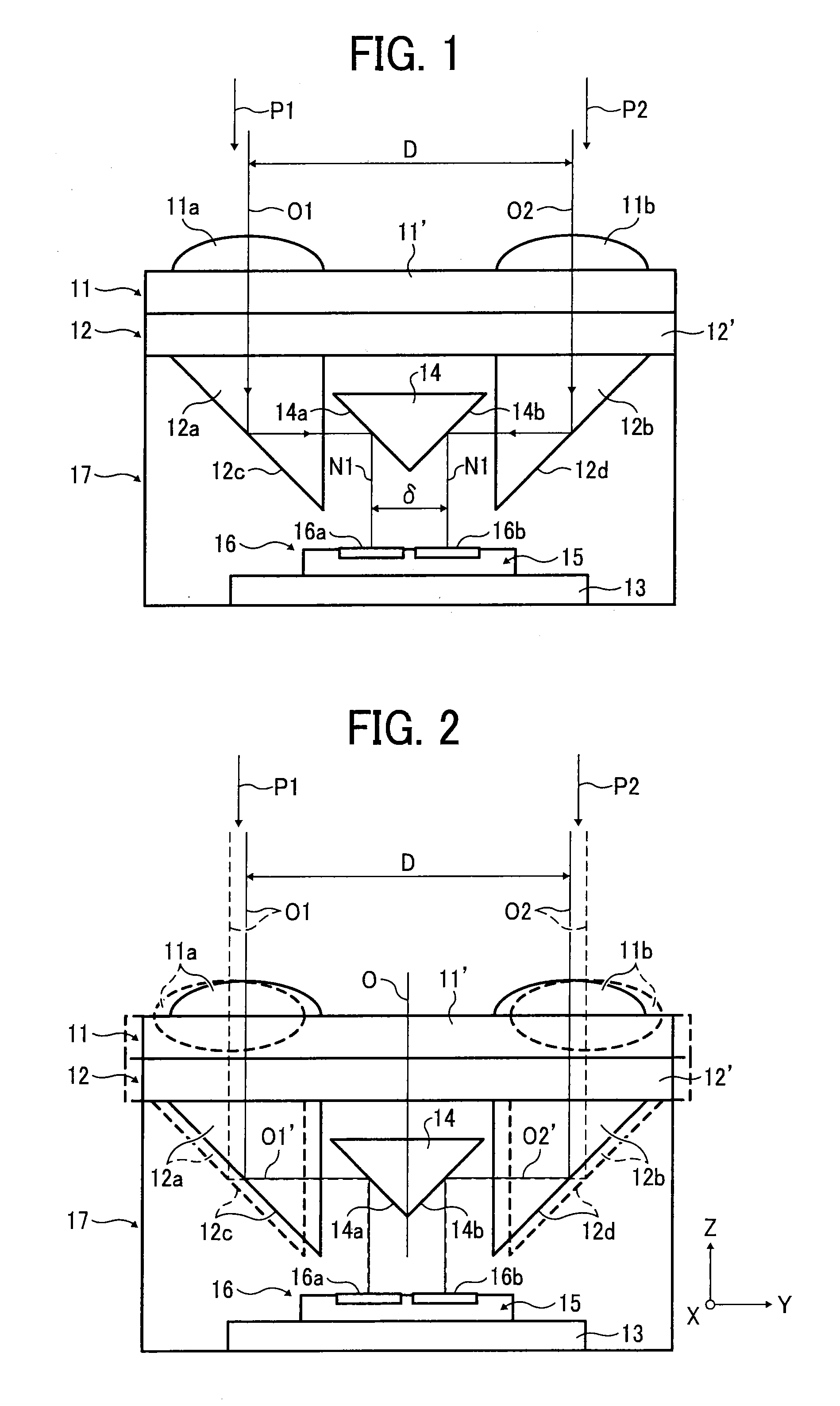
[0054]Hereafter, a preferable embodiment of the present invention will be explained with reference to the drawings. FIG. 1 illustrates a framework of an optical system of a ranging device according to the present invention. As illustrated in FIG. 1, 11 represents a lens array member, 12 represents a mirror array member, 13 represents a circuit board, and 14 represents a medium mirror member. The lens array member 11 has a flat plate part 11′, a pair of ranging lenses 11a and 11b are formed integrally on the flat plate part 11′, optical axes O1 and O2 of the pair of ranging lenses 11a and 11b being parallel to each other. An interval between the optical axis O1 of the ranging lens 11a and the optical axis O2 of the ranging lens 11b is set as a base length D.

[0055]The mirror array member 12 has a flat plate part 12′, and a pair of reflecting members 12a and 12b are formed integrally on the flat plate part 12′. The reflecting member 12a has a reflecting plane 12c corresponding to the r...


PUM


Abstract

A ranging device including: a lens array member which has first and second ranging lenses, optical axes of the pair of ranging lenses being parallel to each other, and first and second optical images of a subject being formed by the first and the second ranging lenses respectively; a mirror array member which has first and second reflecting members, each of the pair of reflecting members being provided with a reflecting plane; a medium mirror member which has first and second reflecting planes, the medium mirror member being arranged between the pair of reflecting members; an imaging element which is configured to convert the first and the second optical images to electronic signals; and an electronic circuit which is configured to calculate a distance to the subject based on the electronic signals output from the imaging element.

Description

CROSS-REFERENCE TO THE RELATED APPLICATION[0001]The entire contents of Japanese patent application No. JP 2010-004475, filed on Jan. 13, 2010, of which the convention priority is claimed in this application, are incorporated hereinto by reference.BACKGROUND OF THE INVENTION[0002]1. Field of the Invention[0003]The present invention relates to a compound-eye-type ranging device, which is capable of resolving a measurement error caused by a variation with time or a change in temperature and stably measuring a distance from a main body of the ranging device to a ranging target, and to a ranging module having the ranging device. The present invention further relates to an image-capturing device which uses the ranging device or the ranging module.[0004]2. Description of the Related Art[0005]Conventionally, a stereo type (compound-eye-type) ranging device is known in which optical axes of the same ranging optical systems are arranged parallel to each other, images of a subject which is a r...

Claims


Application Information

Patent Timeline
IPC IPC(8): G01C3/08
CPCG01C3/085
Inventor OOUCHIDA, SHIGERU
Owner RICOH KK
Why Eureka
Try Eureka