Mesh lighting system for emergency vehicles

a technology for emergency vehicles and lights, applied in the manufacture of electric discharge tubes/lamps, tyre parts, electrical apparatus, etc., can solve the problems of cumbersome retrofit units, difficult to employ on a large variety of vehicles, and require modification of the electrical system of vehicles

Inactive Publication Date: 2011-07-21
9609385 CANADA INC
View PDF121 Cites 18 Cited by
  • Summary
  • Abstract
  • Description
  • Claims
  • Application Information

AI Technical Summary

Benefits of technology

[0007]In order to address the drawbacks of the prior art, there is provided a mesh lighting system for emergency vehicles. The system comprises a plurality of independent signalling light sources each supplied by a dedicated source of energy, a control module, a low powered wireless network connecting the control module with the plurality of light sources, wherein the plurality of independent signalling light sources emit at least one light flash in response to a control signal received from the control module.
[0008]There is also disclosed a method for retrofitting a vehicle with an emergency lighting system. The method comprises providing a plurality of independent signalling light sources each supplied by a dedicated source of energy and placing the light sources about the vehicle so they are visible from a vehicle exterior, each independent signalling light sources comprising a fastener for fastening to the vehicle, and interconnecting each of the independent signalling light sources with a control module using a low powered wireless network. Each of the plurality of independent signalling light sources emits at least one light flash in response to a control signal received from the control module via the low powered wireless network.
[0009]Additionally, there is disclosed a portable kit lighting system for emergency vehicles. The kit comprises a plurality of independent signalling light sources each comprising a dedicated standardised battery, a control module, a sound emitting source, a plurality of replacement batteries, an instruction manual, and a rugged sealable plastic box comprising a foam liner comprising a series of cut-outs configured, one of each of the cut-outs for receiving a respective one of the plurality of independent signalling light sources, the control module, the sound emitting source and the plurality of replacement batteries.
[0010]Other objects, advantages and features of the present invention will become more apparent upon reading of the following non-restrictive description of specific embodiments thereof, given by way of example only with reference to the accompanying drawings.

Problems solved by technology

One drawback of such systems is that they typically require modification to the vehicles electrical system.
This provides difficulties, for example, when security or emergency personnel are operating in regions where the vehicles must be temporarily leased and where modification of the vehicle in question proves an unsuitable alternative.
Such retrofit units are cumbersome and difficult to employ on a large variety of vehicles given the difference in distances between the control / power unit and the light sources.
Also, as the control / power unit is within the automobile and the light sources typically on the outside of the vehicle, a cable must pass through an open window or door jamb which leads to a substandard implementation.
Another drawback is that prior art retrofit systems typically include a large light bar which is cumbersome, not readily portable and difficult to attach to many vehicles which might otherwise be used by emergency personnel.

Method used


Image

  • Mesh lighting system for emergency vehicles
  • Mesh lighting system for emergency vehicles
  • Mesh lighting system for emergency vehicles

Examples


Embodiment Construction

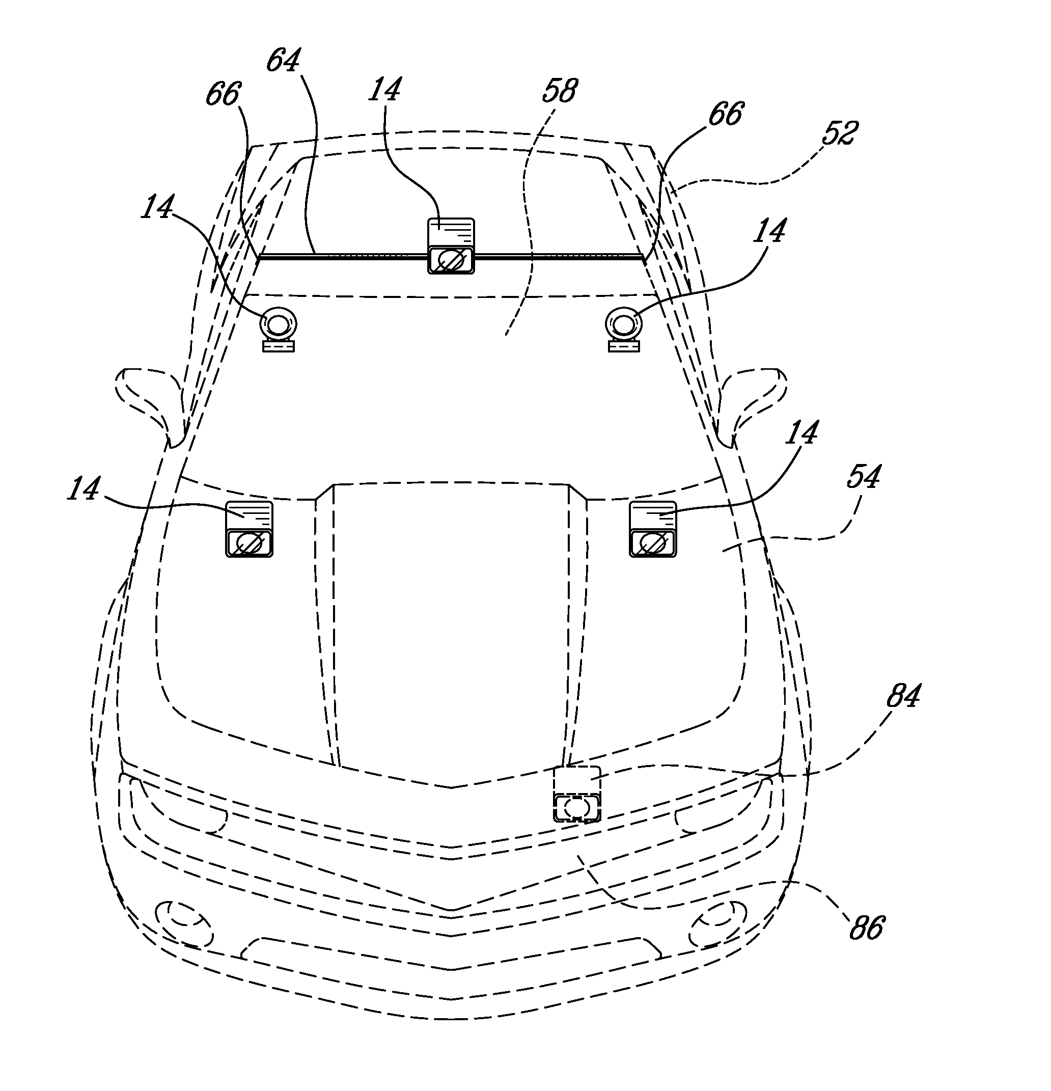
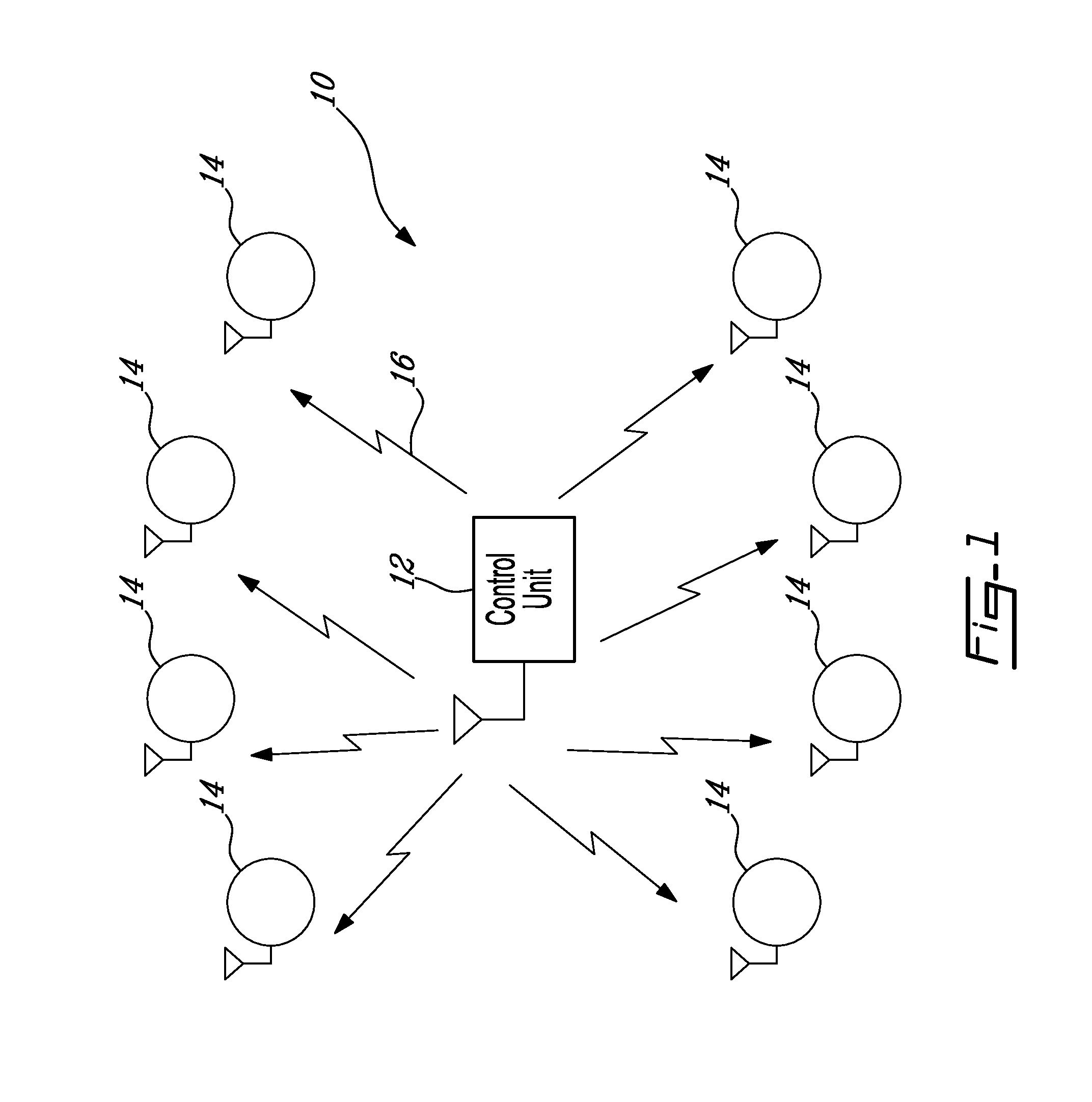
[0021]Referring now to FIG. 1, and in accordance with an illustrative embodiment of the present invention, a mesh lighting system, generally referred to using the reference numeral 10, will now be described. The mesh lighting system is illustratively comprised of a control unit 12 and a plurality of small portable self powered light sources 14 interconnected using wireless communication links as in 16 for the transfer of control signals.

[0022]Still referring to FIG. 1, although the present illustrative embodiment discloses a distinct control unit 12 for powering the plurality of light sources 14, in an alternative embodiment one of the light sources 14 would act as a master and provide the requisite control with the remaining light sources as in 14 slaved to the master.

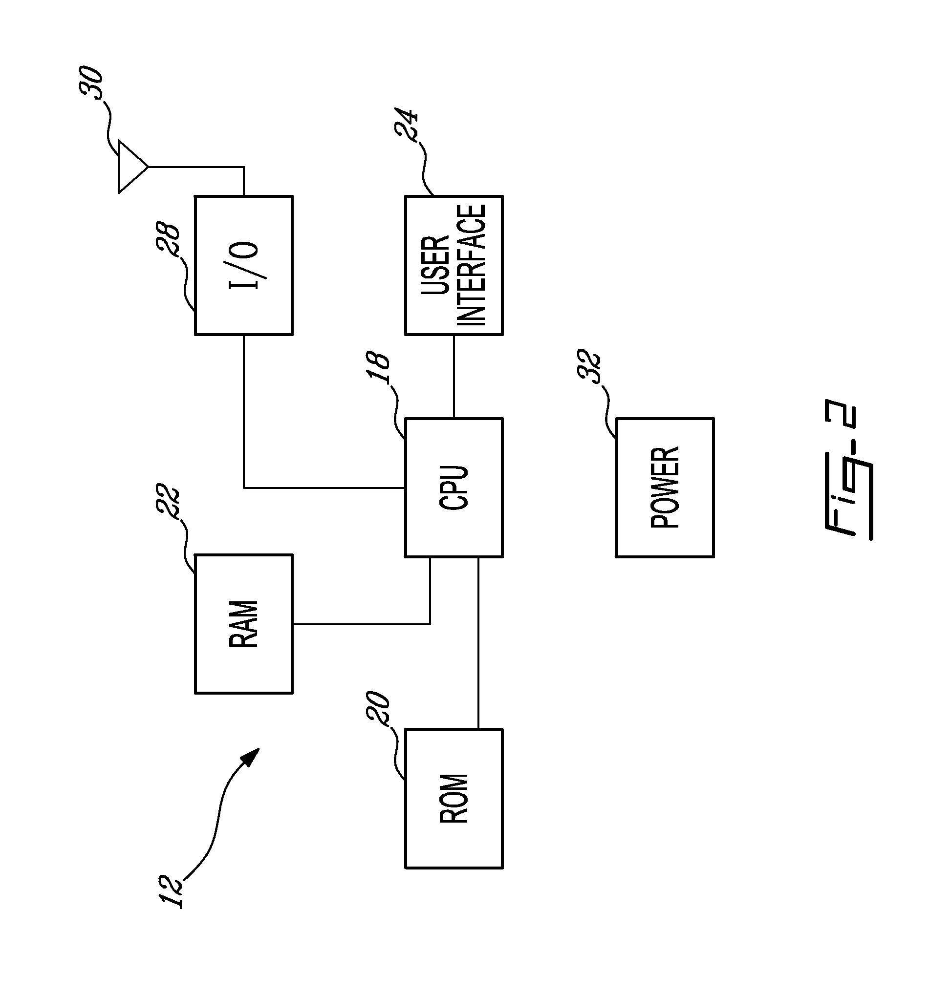
[0023]Referring to FIG. 2, the control unit 12 is illustratively microprocessor controlled and comprises a Central Processing Unit (CPU) 18 and supportive memory (Read Only Memory, ROM, 20, and Random Access Memory, R...


PUM


Abstract

A mesh lighting system for emergency vehicles and method for retrofitting a vehicle with emergency lights is disclosed. The system comprises a plurality of independent signalling light sources each supplied by a dedicated source of energy, a control module, and a low powered wireless network connecting said control module with the plurality of light sources. The plurality of independent signalling light sources emit at least one light flash in response to a control signal received from the control module.

Description

CROSS REFERENCE TO RELATED APPLICATIONS[0001]This application claims benefit, under 35 U.S.C. §119(e), of U.S. provisional application Ser. No. 61 / 296,587, filed on Jan. 20, 2010 which is incorporated herein in its entirety by reference.FIELD OF THE INVENTION[0002]The present invention relates to a mesh lighting system for emergency vehicles. In particular, the present invention relates to portable wireless lighting system suitable for retrofit in a conventional vehicle such as a rental car without requiring modifications to the vehicle.BACKGROUND OF THE INVENTION[0003]Emergency vehicles such as police cars, ambulances and the like are typically equipped with visual signalling such as flashing lights and strobes, to indicate their presence to other road users. Such flashing lights and strobes are typically hardwired into the electrical system of the vehicle in question. Other such lights may be retrofit by attaching a light unit to the automobile and taking advantage, for example, o...

Claims


Application Information

Patent Timeline
Patent Type & Authority Applications(United States)
IPC IPC(8): B60Q1/26B60Q1/14H01J9/24B60Q7/00
CPCB60Q1/2611B60Q1/2615B60Q2900/30B60Q2900/10B60Q1/52B60Q1/2607B60Q1/2661B60Q1/2696B60Q1/46B60Q5/00B60Q7/00B60C5/00
Inventor FORD, TIMOTHY D. F.
Owner 9609385 CANADA INC
Why Eureka
Try Eureka