Light pen
A light pen and light detection technology, which is applied in the direction of telephone structure, telephone communication, instruments, etc., can solve the problems of increasing the weight and volume of the light pen, misunderstanding, fatigue, etc.
- Summary
- Abstract
- Description
- Claims
- Application Information
AI Technical Summary
Problems solved by technology
Method used
Image
Examples
Embodiment 1
[0050] figure 1 is a schematic diagram showing a light pen according to a first exemplary embodiment of the present invention.
[0051] refer to figure 1 , the light pen 100 includes a main body 110 , a light detection module 120 , a control module 130 , a light generation module 140 and a power supply module 150 .
[0052] The main body 110 has a cylindrical shape, and has an inner space to accommodate the light detection module 120 , the control module 130 , the light generation module 140 and the power supply module 150 . An opening 112 is formed at one end of the main body 110, and light generated from the light generating module 140 exits from the opening 112 .
[0053] The light detection module 120 is disposed in the main body 110 . The light detection module 120 detects the image light 10 input from an external source. Image light 10 is generated from a display device such as a liquid crystal display device. The light detection module 120 is capable of detecting w...
Embodiment 2
[0066] figure 2 is a schematic diagram showing a light pen according to a second exemplary embodiment of the present invention. In Embodiment 2, all elements except the light generating module represent the same elements in Embodiment 1, and will not be further described below in order to avoid repetition.
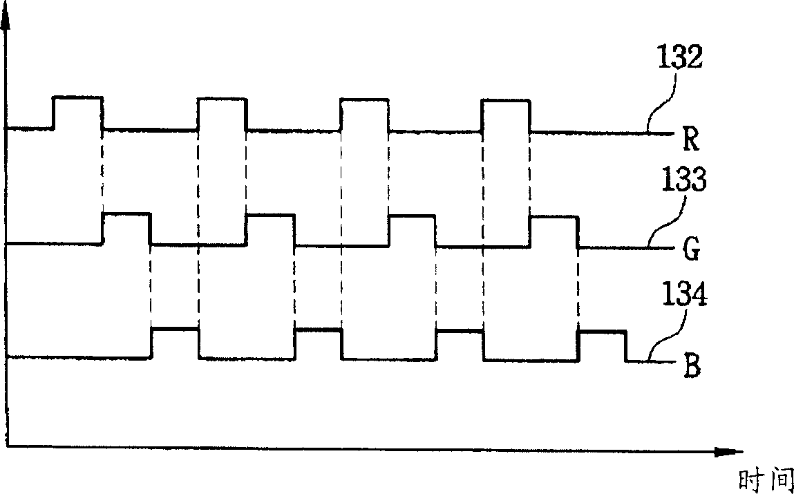
[0067] The light generating module 140 may include various combinations of red light emitting diodes (LEDs) 143 , green LEDs 144 and blue visible light emitting diodes (LEDs) 145 . The red LED produces red visible light 143a having a frequency corresponding to red, the green LED produces green visible light 144a having a frequency corresponding to green, and the blue LED produces blue visible light 145a having a frequency corresponding to blue.
[0068] For example, the light generating module 140 may include only one of a red light emitting diode (LED) 143 , a green light emitting diode (LED) 144 and a blue light emitting diode (LED) 145 . In addition, the light genera...
Embodiment 3
[0079] Figure 4 is a schematic diagram showing a light pen according to a third exemplary embodiment of the present invention, Figure 5 is displayed Figure 4A partial enlarged view of 'A'. In Embodiment 3, all elements except the light concentrating cover represent the same elements in Embodiment 1, and will not be described below to avoid repetition.
[0080] refer to Figure 4 or Figure 5 , the light collecting cover 146 collects the sensing light 142 generated from the light generating module 140 and enhances the brightness of the sensing light 142 .
[0081] The condensing cover 146 may have a cup shape and be disposed near the opening 112 . The light generating module 140 connected to the control module 130 is disposed within the light collecting cover 146 . The sensing light 142 generated from the light generating module 140 is reflected from the light collecting cover 146, and the sensing light 142 is concentrated.
[0082] A light reflection layer 147 may al...
PUM
 Abstract
Description
Claims
Application Information
 - R&D
- Intellectual Property
- Life Sciences
- Materials
- Tech Scout
- Unparalleled Data Quality
- Higher Quality Content
- 60% Fewer Hallucinations
Browse by: Latest US Patents, China's latest patents, Technical Efficacy Thesaurus, Application Domain, Technology Topic, Popular Technical Reports.
© 2025 PatSnap. All rights reserved.Legal|Privacy policy|Modern Slavery Act Transparency Statement|Sitemap|About US| Contact US: help@patsnap.com


