Digital coding method using light flashing frequence to express information

A technology for digital encoding and expressing information, which is applied in the field of electronic signal encoding and can solve problems such as high cost and complex encoding methods.

Active Publication Date: 2005-03-30
HISENSE +1
View PDF1 Cites 15 Cited by
  • Summary
  • Abstract
  • Description
  • Claims
  • Application Information

AI Technical Summary

Problems solved by technology

This encoding method is very complicated and expensive, and it is difficu

Method used


Image

  • Digital coding method using light flashing frequence to express information
  • Digital coding method using light flashing frequence to express information
  • Digital coding method using light flashing frequence to express information

Examples


Embodiment 1

[0021] Example 1. A digital encoding method that expresses information by the number of light flickers, its circuit principle is as follows

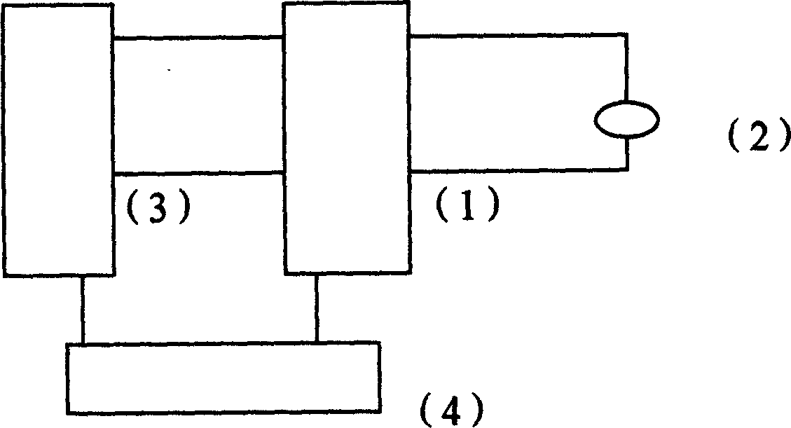
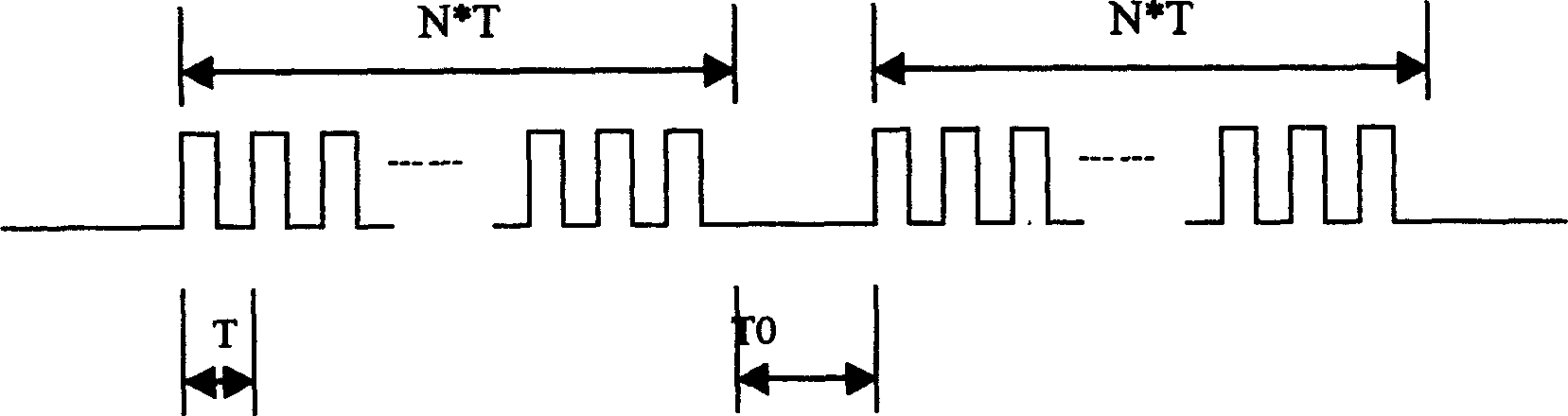
[0022] figure 1 As shown, the encoding timing is as figure 2 shown. Its light-emitting device adopts monochrome light-emitting diode. It includes the following steps:

[0023] ①Design a pulse switch circuit (1), which can control the light-emitting device (2) to emit light flicker pulses, and this circuit is also connected with the electric quantity or non-electric quantity sensor (3), which can express electric quantity or non-electric quantity information as light flicker pulses , the above circuit also includes a power supply (4);

[0024] ② Every time the light-emitting device is turned on and off, that is, it is called flashing once, and each flashing has a fixed cycle T (seconds), and the duration of the flashing and flashing in a cycle is T / 2;

[0025] ③The coding value of the light-emitting device that flashes N times cont...

Embodiment 2

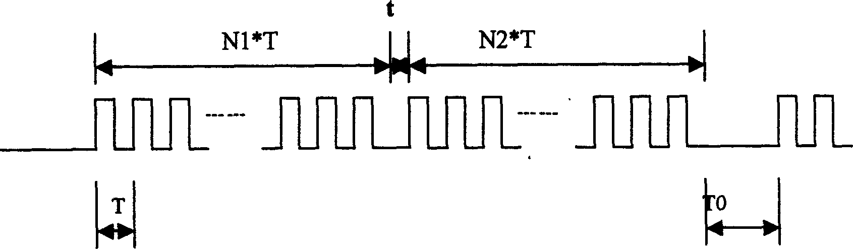
[0028] Example 2. A digital encoding method that expresses information by the number of light flashes, the encoding sequence is as follows image 3 shown. Its light-emitting device is a light-emitting diode that emits two kinds of multicolor light, red and white. The digits of the digital code are distinguished by the color of the light, in which white corresponds to the ones digit and red corresponds to the tens digit. White blinks N1 times continuously, red blinks N2 times continuously, and the digital code value is N=N2×10+N1, where N1 and N2 are both positive integers and <10. The transition time t between different colors is the extinguishing time, t≥0. This is a decimal encoding method. All the other steps are the same as in Example 1.

Embodiment 3

[0029] Example 3. A digital encoding method that expresses information by the number of light flashes, the encoding sequence is as follows Figure 4 shown. The light emitting device is a light emitting diode emitting three polychromatic lights. It uses the luminous color to distinguish the digits of the digital code. The first white color corresponds to the ones digit, the second red color corresponds to the tens digit, and the third blue color corresponds to the hundreds digit. The first white color flashes N1 times continuously, the second red color flashes N2 times continuously, and the third blue color flashes N3 times continuously, and the digital code value is N=N3×100+N2×10+N1, where N1, N2, N3 are all positive integers and <10, the transition time t between different colors is the extinguishing time, t≥0. This is also a decimal encoding method. All the other steps are still the same as in Example 1.

[0030] Embodiments 1 to 3 are simple in structure, accurate and...


PUM


Abstract

The method includes following steps: designing pulse switching circuit connected to sensor in electric quantity or non electric quantity for controlling light emitting device to send out pulses of optical flare; defining fixed cycle T of each flare, and bright and extinguished durations in cycle are half to half; N times of continuous flare express coded number N, and extinguished state between two numbers as interval To; N is outputting coded digital information; setting up correspondence list between coded number and information in advance etc. light emitting devices in multiple colors can be utilized to distinguish digit positions of coded numbers. For example, N1, N2, and N3 times of continuous flare in different colors means that the coded digit number N is N3X100+N2X10+N1. Transfer time t between different colors is a blank interval. Number is coded in decimal system or in M scale. Features are: simple, and high reliability.

Description

technical field [0001] The invention belongs to the technical field of electronic signal coding, and more specifically relates to the design of a digital coding method for expressing information by light flicker times. Background technique [0002] In many electrical appliances or devices, due to insufficient resources or in order not to increase the cost, no or little information is provided on the inner workings. The currently applied methods for providing information include: using a display screen to display, using a combination of multiple signal lights to display, or using sound prompts, and the like. Some of these methods are too expensive, some can provide less information, and some are too complicated to identify. [0003] Chinese Patent No. 01119110.4 provides a coding method for optoelectronic information. It can encode information such as graphics, images, documents, files and compressed files using the same or different bases, and the...

Claims


Application Information

Patent Timeline
IPC IPC(8): H03M7/00H03M7/14
Inventor 陈益军
Owner HISENSE
Why Eureka
Try Eureka