Three-phase power rectification LC high-PF filtering direct-current high-voltage direct-drive LED circuit

An LED circuit, DC high voltage technology, applied in the field of electronics, can solve the problems of not meeting the index requirements of high-power LED lamps, reducing the power factor of the driving power supply, etc., achieving good social and economic benefits, improving luminous efficiency, and reducing costs.

Inactive Publication Date: 2014-11-05
HEFEI SPRUCE OPTOELECTRONICS TECH
View PDF8 Cites 16 Cited by
  • Summary
  • Abstract
  • Description
  • Claims
  • Application Information

AI Technical Summary

Problems solved by technology

The light stroboscopic problem of LED is caused by the voltage and current ripple of driving LED. For the common three-phase rectification and filtering technology, the application of high-voltage capacitors to directly filter the rectified high voltage can easily reduce the voltage and current ripple to overcome the light stroboscopic , but it has a serious technical problem, that is, the power factor PF of the driving power supply will be greatly reduced, and it cannot meet the PF index requirements of high-power LED lamps. It is necessary to specially design and develop high-PF three-phase direct-drive LED technology

Method used


Image

  • Three-phase power rectification LC high-PF filtering direct-current high-voltage direct-drive LED circuit
  • Three-phase power rectification LC high-PF filtering direct-current high-voltage direct-drive LED circuit
  • Three-phase power rectification LC high-PF filtering direct-current high-voltage direct-drive LED circuit

Examples


Embodiment 1

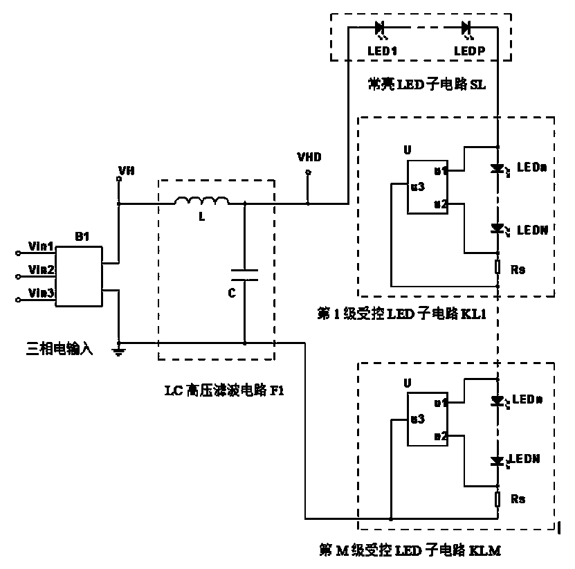
[0029] Such as figure 1 As shown, a three-phase electric rectification LC high PF filter DC high-voltage direct drive LED circuit, including a three-phase full-wave rectifier, an LC high-voltage filter circuit, a constant bright LED sub-circuit and a controlled LED circuit; wherein,

[0030] The three-phase full-wave rectifier B1 includes three three-phase AC input terminals Vin1, Vin2, Vin3, a rectified high voltage output terminal VH and a reference ground terminal GND.

[0031] This embodiment provides an LC high-voltage filter circuit F1, which includes an inductor L and a high-voltage capacitor C. Among them, the inductor L and the capacitor C are connected in series, one end of the inductor L is connected to the rectified high-voltage output terminal VH, one end of the capacitor C is connected to the reference ground GND, and the common terminal of the inductor L and the high-voltage capacitor C is the DC high-voltage output terminal of the LC high-voltage filter circuit...

Embodiment 2

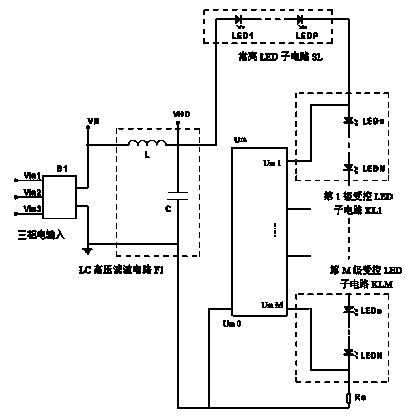
[0037] Such as figure 2 As shown, the difference between this embodiment and Embodiment 1 lies in that the structure of the controlled LED circuit is different.

[0038] In this embodiment, the controlled LED circuit also includes a multi-level control multi-output direct drive LED integrated circuit Um and a current sampling resistor Rs; the multi-level control multi-output direct drive LED integrated circuit Um is provided with multiple control terminals (Um 1 -Um M) and a direct-drive LED integrated circuit with a zero-potential reference terminal Um 0; among them, the controlled LED sub-circuit (KL 1-KL M) includes LED groups, and the LED groups include several LEDs in series in the same direction (LED n- LED N); the current inflow end of one LED group is connected to a control end of the second direct drive LED integrated circuit Um, one end of the current sampling resistor Rs is connected to the current outflow end of the last stage controlled LED sub-circuit KL M, and ...

Embodiment 3

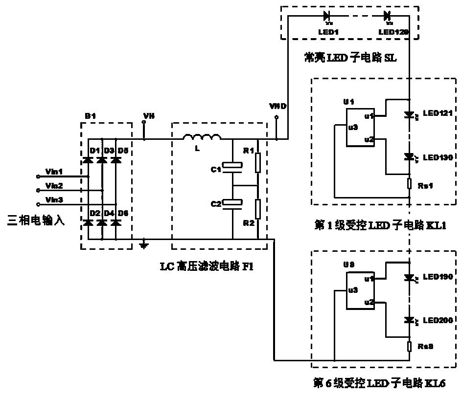
[0042] Such as image 3 As shown, the difference between this embodiment and Embodiment 1 is that a specific circuit structure of a rectified LC high PF filtered DC high voltage direct drive LED circuit suitable for 120W three-phase power is provided.

[0043] This implementation provides another LC high-voltage filter circuit F1, which includes an inductor L, a first high-voltage electrolytic capacitor C1, a second high-voltage electrolytic capacitor C2, a first discharge resistor R1, and a second discharge resistor R2. One end of the inductor L is connected to the rectified high-voltage The output terminal VH and the other end of the inductor L are respectively connected to the positive pole of the first high-voltage electrolytic capacitor C1 and one end of the first discharge resistor R1, and the negative pole of the first high-voltage electrolytic capacitor C1 is respectively connected to the positive pole of the second high-voltage electrolytic capacitor C2 and the second ...


PUM


Abstract

The invention discloses a three-phase power rectification LC high-PF filtering direct-current high-voltage direct-drive LED circuit. The three-phase power rectification LC high-PF filtering direct-current high-voltage direct-drive LED circuit comprises a three-phase full-wave rectifier, a high-PF LC high-voltage filter circuit, a normally-on LED sub-circuit, a plurality levels of controlled LED sub-circuits and the like, wherein a three-phase alternating current is processed through three-phased full-wave rectification, so that an alternating-current and direct-current ripple high voltage is obtained, the alternating-current and direct-current ripple high voltage is then filtered by the high-PF LC high-voltage filter circuit so that an ideal direct-current high voltage can be obtained, and under control of a direct-drive integrated circuit, the direct-current high voltage directly drives LEDs, and the multiple levels of controlled LED sub-circuits are controlled by the direct-drive LED integrated circuit; when the transient voltage of a current sampling resistor is smaller than some threshold voltage, loads of the LED sub-circuits are short circuited by the integrated circuit; when the transient voltage of the current sampling resistor is larger than or equal to some threshold voltage, the loads of the LED sub-circuits are connected in by the integrated circuit. The three-phase power rectification LC high-PF filtering direct-current high-voltage direct-drive LED circuit has the advantages of being high in power supply conversion efficiency, large in power factor, small in current ripple, good in light flash resistance, high in reliability, low in cost and the like.

Description

technical field [0001] The invention belongs to the field of electronics, and in particular relates to a three-phase electric rectification LC high PF filter direct current high voltage direct drive LED circuit. Background technique [0002] As a new generation of light-emitting devices, light-emitting diodes (LEDs) have the outstanding advantages of high efficiency and energy saving, and are constantly replacing traditional lighting technologies and are widely used. Compared with switching power supply drive LED technology, single-phase AC mains direct drive LED technology has the characteristics of high reliability. Compared with single-phase AC direct-drive LED technology, three-phase electric direct-drive LED technology has the advantages of high driving voltage, low current, and low wire and cable costs, and is especially suitable for high-power LED road lighting such as street lamps. For this technology, the inventor has obtained the national utility model patent "Thr...

Claims


Application Information

Patent Timeline
Patent Type & Authority Applications(China)
IPC IPC(8): H05B37/02
Inventor 赵天鹏李雪白
Owner HEFEI SPRUCE OPTOELECTRONICS TECH
Why Eureka
Try Eureka