
Method and Apparatus for Contention-Based Granting in a Wireless Communication Network

a wireless communication network and wireless communication technology, applied in electrical devices, network traffic/resource management, wireless commuication services, etc., can solve the problems of reducing the signaling overhead, affecting the success of transmission, and correspondingly entail significant and undesirable increases in the signaling overhead. , to achieve the effect of reducing the signaling load of the pdcch

Active Publication Date: 2011-07-21
TELEFON AB LM ERICSSON (PUBL)
View PDF6 Cites 86 Cited by
  • Summary
  • Abstract
  • Description
  • Claims
  • Application Information

AI Technical Summary

Benefits of technology

[0014]In at least one such embodiment, the user terminal determines whether to make the transmission based on the state of its uplink transmit buffer, e.g., in dependence on whether it has data to send. The user terminal further determines which particular subset of uplink resource blocks to use within the allocated range via random selection, for example. Randomizing subset selection decreases the likelihood of actual contention between two or more user terminals making contention-based uplink transmissions responsive to the contention-based uplink grant message. As a further non-limiting example of reducing instances of actual contention, individual ones in a plurality of user terminals may be configured to make a probabilistic decision about whether to attempt a contention-based uplink transmission, such that the probability at which individual terminals in a group attempt a contention based uplink transmission in response to the contention-based uplink grant message varies across terminals in the group, and lowers the chance that they all will make such a transmission, even in cases where they all have uplink data to send.

Problems solved by technology

However, with several users in a cell, collision probability becomes an issue for contention-based transmissions on the uplink.
If several user terminals attempt a contention-based uplink transmission responsive to the same contention-based uplink grant—i.e., on the same set of uplink resources allocated by a contention-based uplink grant—a transmission collision results and it is likely that none of the transmissions will be successful.
One approach to reducing the likelihood of collision involves signaling more than one contention-based uplink grant within a given sub-frame but such approaches correspondingly entail significant and undesirable increases in the signaling overhead.

Method used


Image

  • Method and Apparatus for Contention-Based Granting in a Wireless Communication Network
  • Method and Apparatus for Contention-Based Granting in a Wireless Communication Network
  • Method and Apparatus for Contention-Based Granting in a Wireless Communication Network

Examples


Embodiment Construction

ample case.

[0019]FIG. 4 is a logic flow diagram of one embodiment of a method of processing at a wireless communication network base station.

[0020]FIG. 5 is a logic flow diagram of one embodiment of a method of processing at a user terminal.

[0021]FIGS. 6A and 6B illustrate a table of example Modulation and Coding Scheme, “MCS”, selections, which can be used to control the MCS parameters adopted by a user terminal for making a contention-based uplink transmission.

[0022]FIG. 7 illustrates a table of access probability control values, which can be used to control the probability at which individual user terminals decide whether to make a contention-based uplink transmission.

DETAILED DESCRIPTION

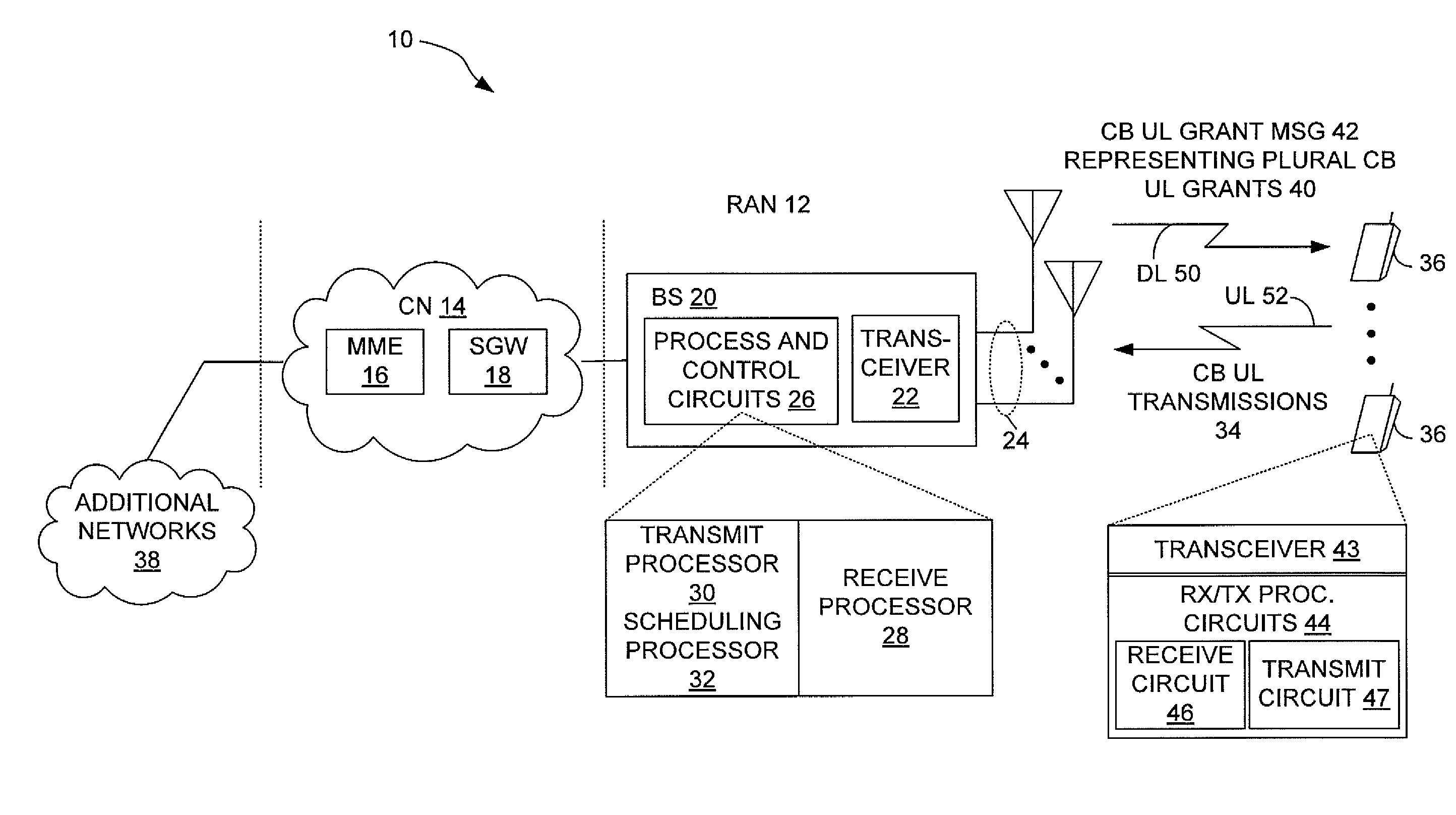
[0023]FIG. 1 partially illustrates a wireless communication network 10, including a Radio Access Network, “RAN”, 12 and an associated Core Network, “CN”, 14. In one example embodiment, the wireless communication network 10 comprises a 3GPP LTE network, wherein the RAN 12 is an LTE-based radio acc...


PUM


Abstract

In one aspect of the disclosed teachings, associating a plurality of contention-based uplink grants with a range of uplink resource blocks allows one contention-based uplink grant message to signal the entire plurality of grants. As an example in the LTE context, the signaling load on the PDCCH is reduced by using a single contention-based uplink grant message to signal a plurality of contention-based uplink grants. The message indicates an allocated set of uplink resource blocks and the number of separate uplink resource grants represented by the set is known or signaled, such that user terminals recognize that separate subsets of uplink resource blocks within the set each correspond to a separate contention-based uplink grant. Information included in the contention-based uplink grant message, or otherwise signaled can be used to control the probability at which the user terminals attempt contention-based uplink transmissions and / or to control the MCS used for such transmissions.

Description

RELATED APPLICATIONS[0001]This application claims priority under 35 U.S.C. §119 from the U.S. provisional patent application identified by Application No. 61 / 295,383 and filed on 15 Jan. 2010, which is incorporated herein by reference.BACKGROUND[0002]In 3rd Generation Partnership Project, “3GPP”, Long Term Evolution, “LTE”, networks, a dormant user terminal is known at the cell level and retains its Radio Resource Connection, “RRC”, and established radio bearers. However, a user terminal entering dormancy activates discontinuous reception / transmission, “DRX”, for power savings during periods of temporary inactivity. Because user terminals are quickly moved into the dormancy sub-state, quick reactivation of the user terminal is crucial for good system performance. Consequently, the 3GPP Release-10, also referred to as LTE-Advanced, target for the dormant to active transition is 10 ms, excluding the DRX cycle—see the 3GPP Technical Specification, “TS”, 36.913 for more information.[000...

Claims


Application Information

Patent Timeline
IPC IPC(8): H04W72/04
CPCH04W74/006H04W74/0833H04W74/004H04W72/04H04W72/042H04W28/04H04W72/23
Inventor WAGER, STEFANENBUSKE, HENRIKFURUSKAR, ANDERSLARMO, ANNALINDSTROM, MAGNUSMEYER, MICHAEL
Owner TELEFON AB LM ERICSSON (PUBL)
Learn More