Manual Spinal Traction Device

a cervical traction and headgear technology, applied in the field of manual cervical traction headgear, can solve the problems of pain, injury, and inability to provide traction force substantially parallel to the central axis of the patient's body, and achieve the effect of adding comfort to the patien

Inactive Publication Date: 2011-07-21
MACKOWIAK PAULA
View PDF7 Cites 11 Cited by
  • Summary
  • Abstract
  • Description
  • Claims
  • Application Information

AI Technical Summary

Benefits of technology

[0011]The head-strap may have a high-friction material on the second surface at positions where the head-strap contac...

Problems solved by technology

However, such traction devices may cause discomfort, pain, or even damage to the temporomandibular joint (“TMJ”), the jaw, or the teeth of the patient.
However, such traction devices cannot provide traction force substantially parallel to a central axis of the patient's body.
Such devices are not designed for manual traction—devices according to this design do not ...

Method used


Image

  • Manual Spinal Traction Device
  • Manual Spinal Traction Device
  • Manual Spinal Traction Device

Examples


Embodiment Construction

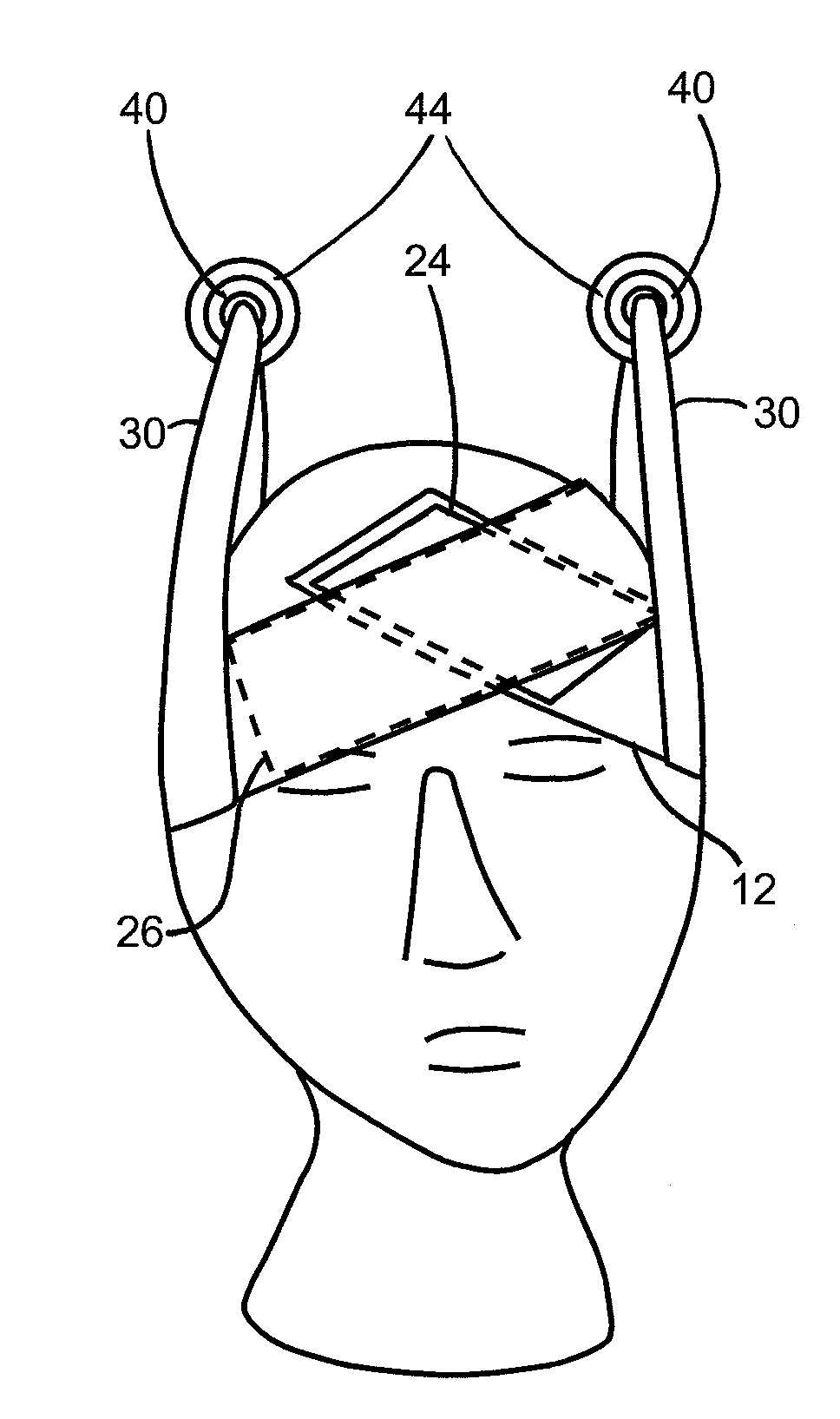
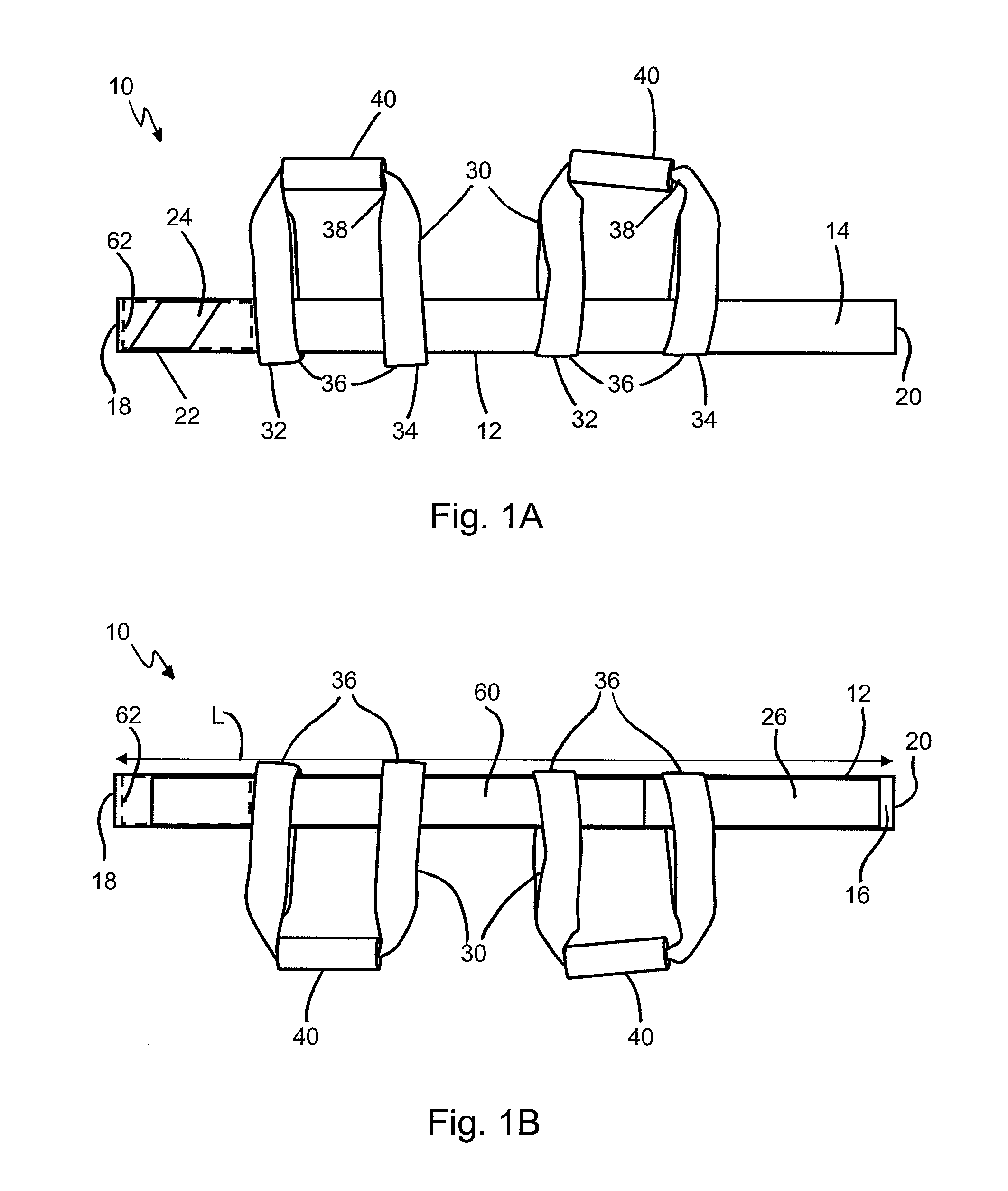
[0019]FIGS. 1A and 1B depict a device 10 according to an embodiment of the invention which includes a head-strap 12 having a first side 14, corresponding with an outside of the device 10, and a second side 16, corresponding with an inside (or head-contacting side) of the device 10. The head-strap 12 has a fixed end 18 and a positional end 20. A fastener 22 is affixed to the head-strap 12.

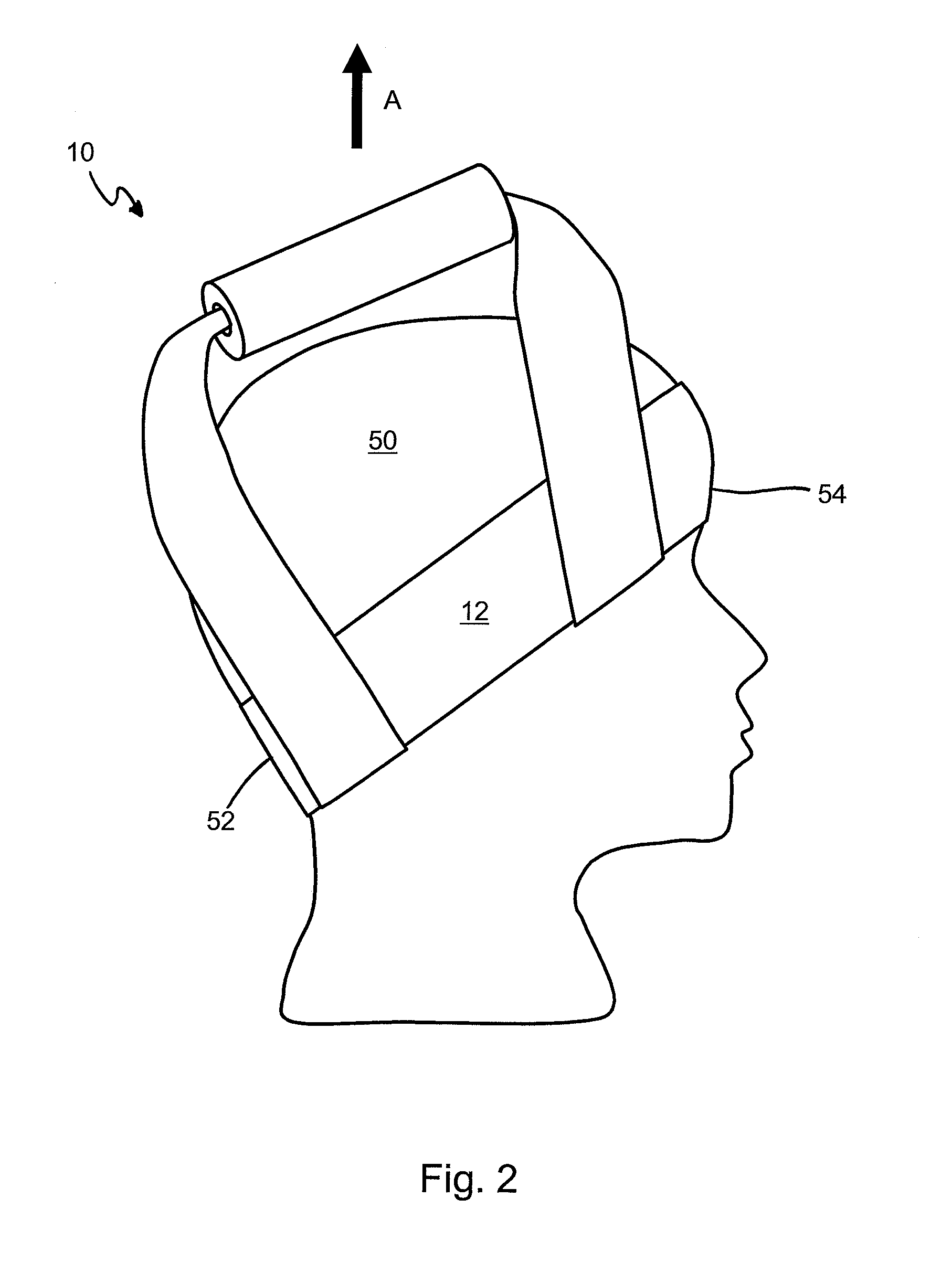
[0020]The head-strap 12 is configured to wrap around a circumference of a patient's head. FIG. 2 depicts where, when arranged on a patient's head 50, the head-strap 12 is configured to engage the base of the skull 52 on the caudal side of the head 50, and the forehead at the supraorbital ridge 54 on the rostral side of the head 50. The head-strap 12 may have a length “L” selected such that various patient head sizes may be accommodated The fastener 22 is configured such that the head-strap 12 may be fastened to itself by way of the fastener 22 once the head-strap 12 is wrapped around the patient's h...


PUM


Abstract

A manual traction device is disclosed comprising a head-strap configured to wrap around a circumference of a patient's head. A fastener is affixed to the head-strap, configured such that the head-strap may be fastened to itself. The fastener may be a hook-and-loop type fastener. One or more handle-straps are provided, which are slidably attached to the head-strap. In this manner, the position of the handle-strap(s) may be adjusted relative to the length of the head-strap. Using the disclosed manual traction device situated on a patient as more fully described herein, a therapist may apply a pulling force to the handle-strap(s) in a cephalad direction, thereby causing a traction force to be transmitted to the patient's spine.

Description

FIELD OF THE INVENTION[0001]The present invention relates generally to a device for applying traction to the cervical spinal area, and in particular, to a headgear for manual cervical traction.BACKGROUND OF THE INVENTION[0002]Cervical traction is a widely accepted technique used by chiropractors, physical therapists, and other professionals (collectively, “therapists”) for providing pain relief and improving motion in patients. While a patient is lying in a supine position, a trained therapist applies force so as to stretch the cervical spine, opening the spaces between the vertebrae, and elongating the layers of connective tissue throughout the spine. The therapist may use only their hands to perform the technique, or a device for providing traction may be used.[0003]Devices to aid in applying traction force to the cervical region have been designed, but each of the previous attempts suffers certain shortcomings. Some prior art devices utilize halters which generally engage the pat...

Claims


Application Information

Patent Timeline
IPC IPC(8): A61F5/00
CPCA61H1/0218A61H1/0296A61H2203/0456A61H2201/1607A61H2201/1253
Inventor MACKOWIAK, PAULA
Owner MACKOWIAK PAULA
Why Eureka
Try Eureka