Cryosurgical Instrument Insulating System

a cryosurgical and instrument technology, applied in the field of cryosurgical instrument thermal insulation, can solve the problems of not teaching or suggesting a simple and inexpensive mechanism in the background art, and achieve the effects of minimizing the propagation of formed ice balls, low specific thermal conductivity, and high specific thermal conductivity

Inactive Publication Date: 2011-07-21
ICECURE MEDICAL
View PDF45 Cites 30 Cited by
  • Summary
  • Abstract
  • Description
  • Claims
  • Application Information

AI Technical Summary

Benefits of technology

[0020]In another embodiment, the internal middle section of the shaft comprises a tubular piece from metal or another material with very high specific thermal conductivity, for example, copper, silver, graphite or the like, or a combination thereof. The outer side of the shaft is protected with a tubular piece from a metal, which is compatible with human tissue (stainless steel, titanium or the like, for example). The internal distal section of the shaft is preferably fabricated from a metal tubular piece (or pieces) with relatively low specific thermal conductivity (stainless steel, titanium or the like for example) in order to minimize propagation of a formed ice ball in the backward direction. The internal proximal section of the shaft is a tubular piece from a material with relatively low specific thermal conductivity, such as a metal for example; this minimizes a flux of lower temperatures in the axial direction of the cryosurgical instrument.
[0021]In some embodiments, the instrument comprises two portions which are connected through a quick coupling connection, featuring a male unit and a female unit; the former preferably is connected to the portion with the cryotip, while the latter is in contact with body tissue. For such an embodiment, the material with low specific thermal conductivity is preferably installed so as to minimize the flux of lower temperatures from the male unit to the female unit.
[0022]In a preferred embodiment, the heating means features a gas with high relative humidity; this allows to achieve very high heat transfer coefficient for heating the middle section of the external shaft and, additionally, to heat this middle section of the shaft up to a place of penetration of the cryosurgical instrument into a tissue.
[0023]In another preferred embodiment the heating gas has low relative humidity or a high level of dryness (without wishing to be limited by a single hypothesis, it prevents formation of microorganism colonies in a passageways of the heating gas).
[0024]In a further embodiment of the present invention, there is a displaceable cap, which can be slidingly shifted along the external shaft of the cryosurgical instrument. In its initial position, the cap is adjacent to a bushing with nozzles providing the heating gas and it is joined with this bushing by a set of small magnets, which are installed on the bushing and the cap itself. After penetration of the cryosurgical instrument into a tissue, the cap is shifted until it contacts with the site of tissue penetration of the cryosurgical instrument. In such a way, the cap protects the tissue from contacting the gaseous heating jets. Among other advantages, this protection obviates the need for sterilizing the heating gaseous medium supplied into the nozzles.

Problems solved by technology

The background art does not teach or suggest a simple and inexpensive mechanism for maintaining a controlled temperature differential between material inside a cryosurgical instrument and the external temperature of the shaft, away from the tip.

Method used


Image

  • Cryosurgical Instrument Insulating System
  • Cryosurgical Instrument Insulating System
  • Cryosurgical Instrument Insulating System

Examples


Embodiment Construction

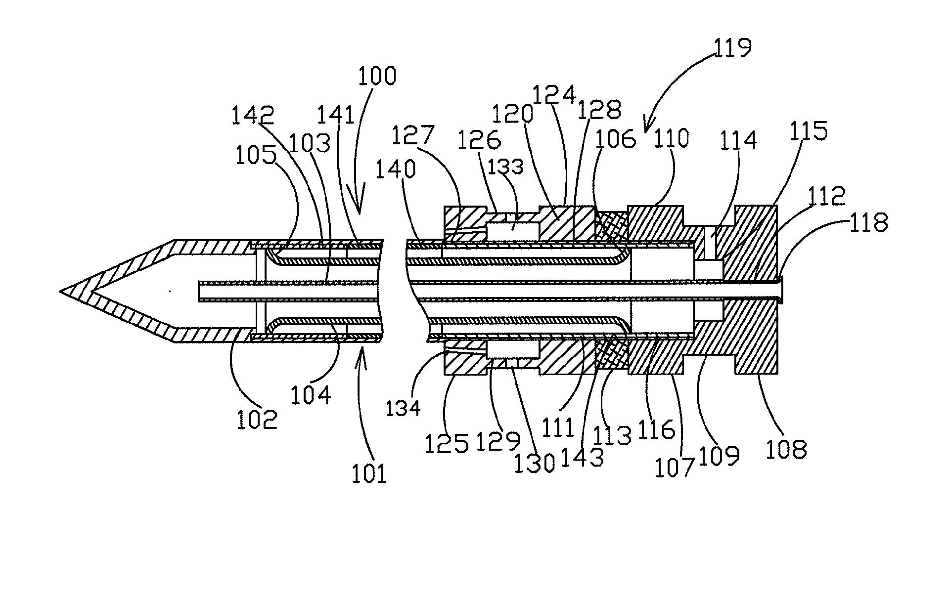
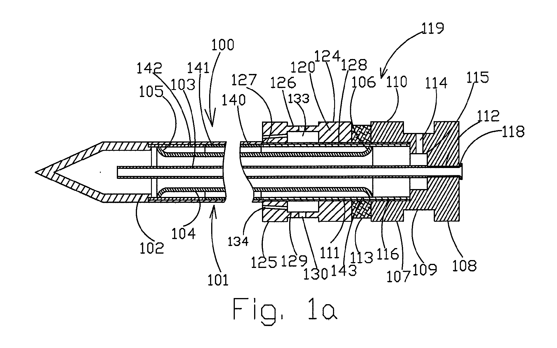
[0041]FIG. 1 shows an axial cross-section of a cryosurgical instrument 100 according to the present invention with heating an external shaft by streams of a gaseous medium, which preferably have a high water content (ie are humidified). This embodiment of cryosurgical instrument 100 comprises the elongated external shaft 101, which terminates at its distal edge with cryotip 102.

[0042]There is a central feeding pipe 103, which is situated in shaft 103. Preferably, the proximal end of the central feeding pipe 103 protrudes from the proximal end of shaft 101. The proximal sections of the elongated external shaft 101 and the central feeding pipe 103 serve for installation of a male unit 119 for quick coupling. The extreme proximal section of the shaft 101 preferably protrudes at least partially to prevent movement past a certain point with regard to male unit 119.

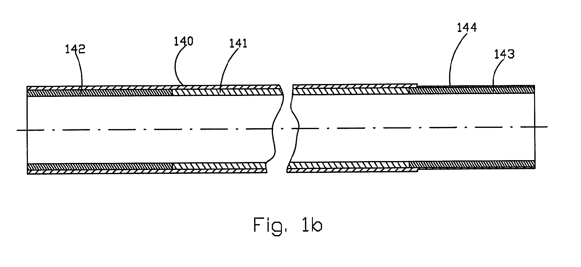
[0043]Thermal insulation of the elongated external shaft 101 is ensured by an intermediate tube 104 with two flanged ends 105...


PUM


Abstract

A device, system and method for controlling the temperature differential between the material within the cryosurgical instrument and the external temperature of the shaft, apart from at the cryotip itself.

Description

FIELD OF THE INVENTION[0001]The present invention is of a device, system and method for thermal insulation for a cryosurgical instrument and in particular, for such a device, system and method for maintaining a controlled external temperature for at least a portion of the probe shaft.BACKGROUND OF THE INVENTION[0002]Cryoprobes (rigid cryosurgical instruments) frequently experience problems of temperature control, particularly with regard to maintaining temperature differential between the contents of the cryoprobe, which are very cold, and the outer shaft, which is desirably maintained at a higher temperature, outside of the tip itself. The outer shaft is in contact with body tissues which may be damaged by excessively cold temperatures, as only the portion of the body tissues which are in contact with the cryotip should be frozen.[0003]At the same time the closed distal end (cryotip) of such a probe must provide in many cases high specific freezing capacity at sufficiently low temp...

Claims


Application Information

Patent Timeline
Patent Type & Authority Applications(United States)
IPC IPC(8): A61B18/02
CPCA61B18/02A61B2018/00005A61B2018/00101A61B2018/00023A61B2018/00095A61B2018/00017
Inventor LEVIN, ALEXANDERTOUBIA, DIDIERKAGANOVICH, MIRONGRUZINSKY, KALMAN
Owner ICECURE MEDICAL
Why Eureka
Try Eureka