Electron vibratory measurement system for measuring mass flow rate

A measurement system, mass flow rate technology, applied in the direction of measuring flow/mass flow, mass flow measurement device, direct mass flowmeter, etc., can solve problems such as expensive

Active Publication Date: 2021-08-03
ENDRESS HAUSER FLOWTEC AG
View PDF49 Cites 0 Cited by
  • Summary
  • Abstract
  • Description
  • Claims
  • Application Information

AI Technical Summary

Problems solved by technology

For this reason, the measurement system has additional but expensive valve controls and additional supply and return fluid lines

Method used


Image

  • Electron vibratory measurement system for measuring mass flow rate
  • Electron vibratory measurement system for measuring mass flow rate
  • Electron vibratory measurement system for measuring mass flow rate

Examples


Embodiment Construction

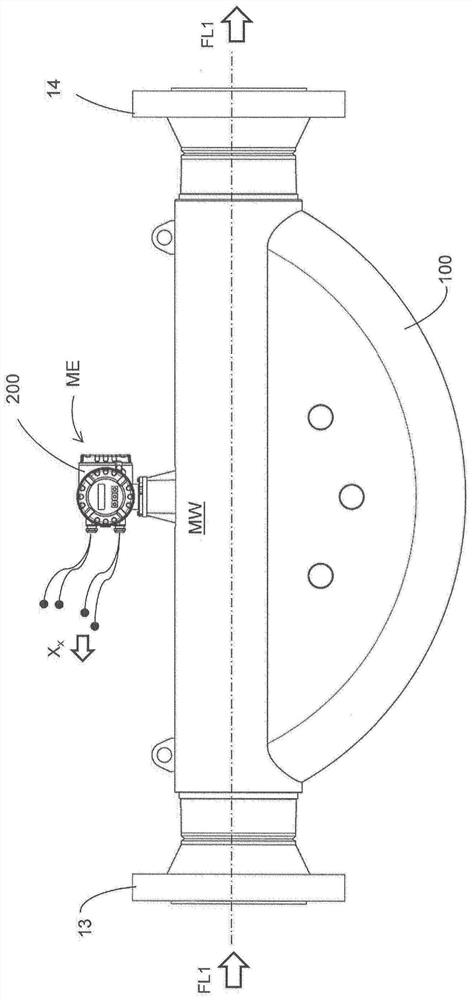
[0082] figure 1 A schematic diagram showing an electro-vibratory measurement system for measuring the mass flow rate m of a flowing fluid FL1 (measurement fluid), optionally with a temporally and / or spatially varying measurement fluid temperature For example gases, liquids or flowable dispersions, the electro-vibratory measuring system is either used to repeatedly determine a mass flow measurement x representing the mass flow rate m instantaneously m . The measuring system can also be designed for determining at least one further measured variable of the fluid FL, namely, for example, a material parameter. The further measured variable may be, for example, density p, viscosity η or, for example, the measured fluid temperature of the fluid flowing through the pipeline

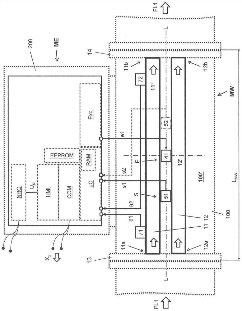
[0083] For this purpose, the measuring system comprises: a transducer device MW for generating a measurement signal at least for measuring the mass flow rate; and a measuring and operating electronics unit ...


PUM


Abstract

The invention relates to a measuring system comprising a measuring and operating electronics unit (ME) and a transducer device electrically connected thereto. The transducer device (MW) has at least one tube through which fluid flows during operation and is caused to vibrate simultaneously; a vibration exciter (41); two vibration sensors (51, 52) on the inlet and outlet sides respectively , for generating vibration signals (s1, s2); and, two temperature sensors (71, 72) on the inlet and outlet sides, respectively, for generating temperature measurement signals (θ1, θ2), the measuring and operating electronics unit (ME) is thermally conductively coupled to the wall of the tube. A measuring and operating electronics unit (ME) is electrically connected to each vibration sensor (51, 52) and also to each temperature sensor (71, 72) and to at least one vibration exciter (41). The measuring and operating electronics unit (ME) is designed to feed electrical energy into at least one vibration exciter (41) in order to achieve a mechanical vibration of the tube (11) by means of an electrical excitation signal (e1). Furthermore, the measuring and operating electronics unit (ME) is designed to generate a mass flow sequence (X m )—that is, a series of time-sequential mass flow measurements (x m,i ), which represents the instantaneous mass flow rate (m) of the fluid such that at least for the reference mass flow rate (m ref )—that is, the specified mass flow rate of the reference fluid flowing through the transducer device, the mass flow measurement value (x m,i →x m,ref ) has nothing to do with the temperature difference.

Description

technical field [0001] The invention relates to an electro-vibratory measurement system, in particular for measuring physical measurement variables of fluids flowing in pipelines. Background technique [0002] In industrial measurement and automation technology, electro-vibration measuring systems - i.e. measuring systems formed by means of electro-vibration transducer devices - are frequently used for the highly accurate determination of the measurement of at least one physically measured variable of a fluid flowing in a pipeline value, the at least one physically measured variable is eg a material parameter such as density and / or a flow parameter such as mass flow rate of a gas, liquid or dispersion. In particular, an electro-vibration measurement system is established in this aspect, wherein the transducer device comprises at least one tube comprising an inner cavity surrounded by a generally metallic wall, wherein an inlet-side first end extends to an outlet Said tube a...

Claims


Application Information

Patent Timeline
Patent Type & Authority Patents(China)
IPC IPC(8): G01F1/84G01F15/02G01F25/00G01F1/74
CPCG01F1/74G01F1/8436G01F1/8477G01F15/022G01F15/02G01F25/10G01F1/78G01F1/8495G01F1/8422G01K3/04G01F15/024G01F1/86G01F1/8413G01F1/8409G01F1/8468G01F1/845
Inventor 恩尼奥·比托克里斯托夫·胡伯阿尔弗雷德·里德
Owner ENDRESS HAUSER FLOWTEC AG
Why Eureka
Try Eureka