
System and method of automatic detection of obstructions for a robotic catheter system

a robotic catheter and automatic detection technology, applied in the field of robotic catheter systems, can solve problems such as death and variety of ailments

Active Publication Date: 2011-07-21
ST JUDE MEDICAL ATRIAL FIBRILLATION DIV
View PDF10 Cites 18 Cited by
  • Summary
  • Abstract
  • Description
  • Claims
  • Application Information

AI Technical Summary

Benefits of technology

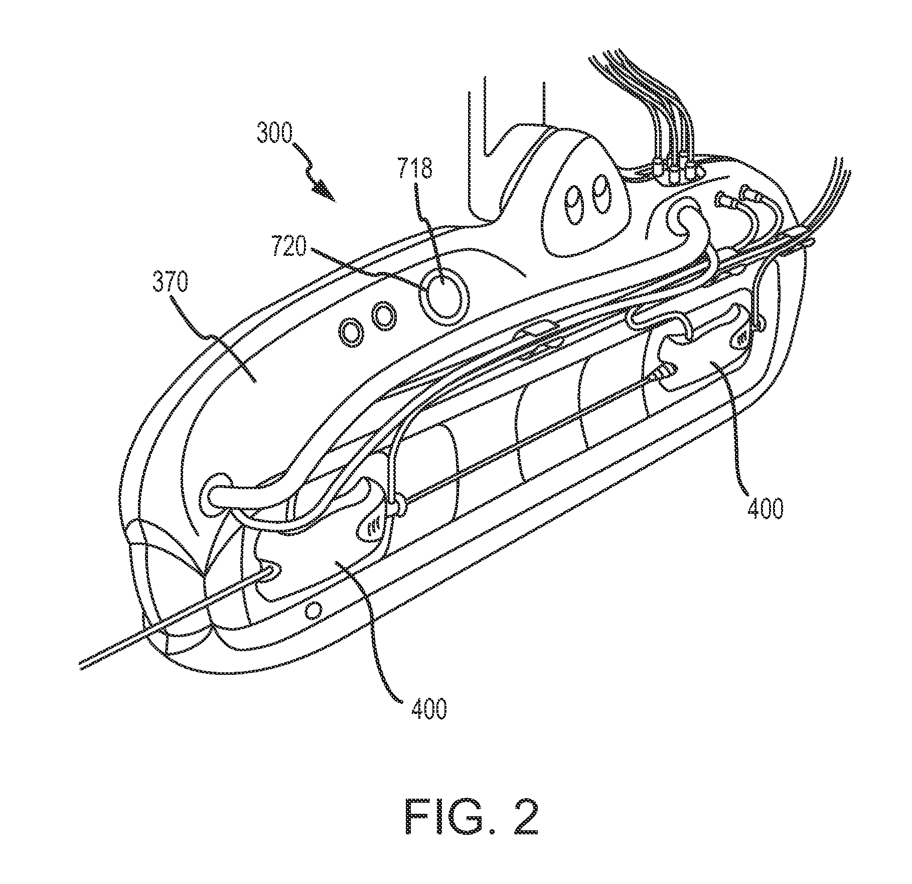
[0010]For the obstruction detection system described above, in one embodiment, the obstruction detection sensors may be ultrasonic sensors or light-emitting sensors. In one embodiment, the obstruction detection system may include obstruction detection sensors located at both ends of the track. In another embodiment, the obstruction detection system may include obstruction detection sensors located at both longitudinal ends of the catheter and sheath manipulation bases. In one embodiment of the obstruction detection system, the obstruction detection sensors enable maintenance of a predetermined distance between the catheter and sheath manipulation bases.
[0016]For the obstruction detection system described above, in one embodiment, the detection means may be an ultrasonic sensor or a light-emitting sensor. In one embodiment of the obstruction detection system, the detection means may include obstruction detection sensors located at both ends of the track. In another embodiment of the obstruction detection system, the detection means may include obstruction detection sensors located at both longitudinal ends of the catheter and sheath manipulation bases. In one embodiment of the obstruction detection system, the obstruction detection sensors may enable maintenance of a predetermined distance between the catheter and sheath manipulation bases.

Problems solved by technology

Arrhythmia can create a variety of dangerous conditions including irregular heart rates, loss of synchronous atrioventricular contractions and stasis of blood flow which can lead to a variety of ailments and even death.

Method used


Image

  • System and method of automatic detection of obstructions for a robotic catheter system
  • System and method of automatic detection of obstructions for a robotic catheter system
  • System and method of automatic detection of obstructions for a robotic catheter system

Examples


Embodiment Construction

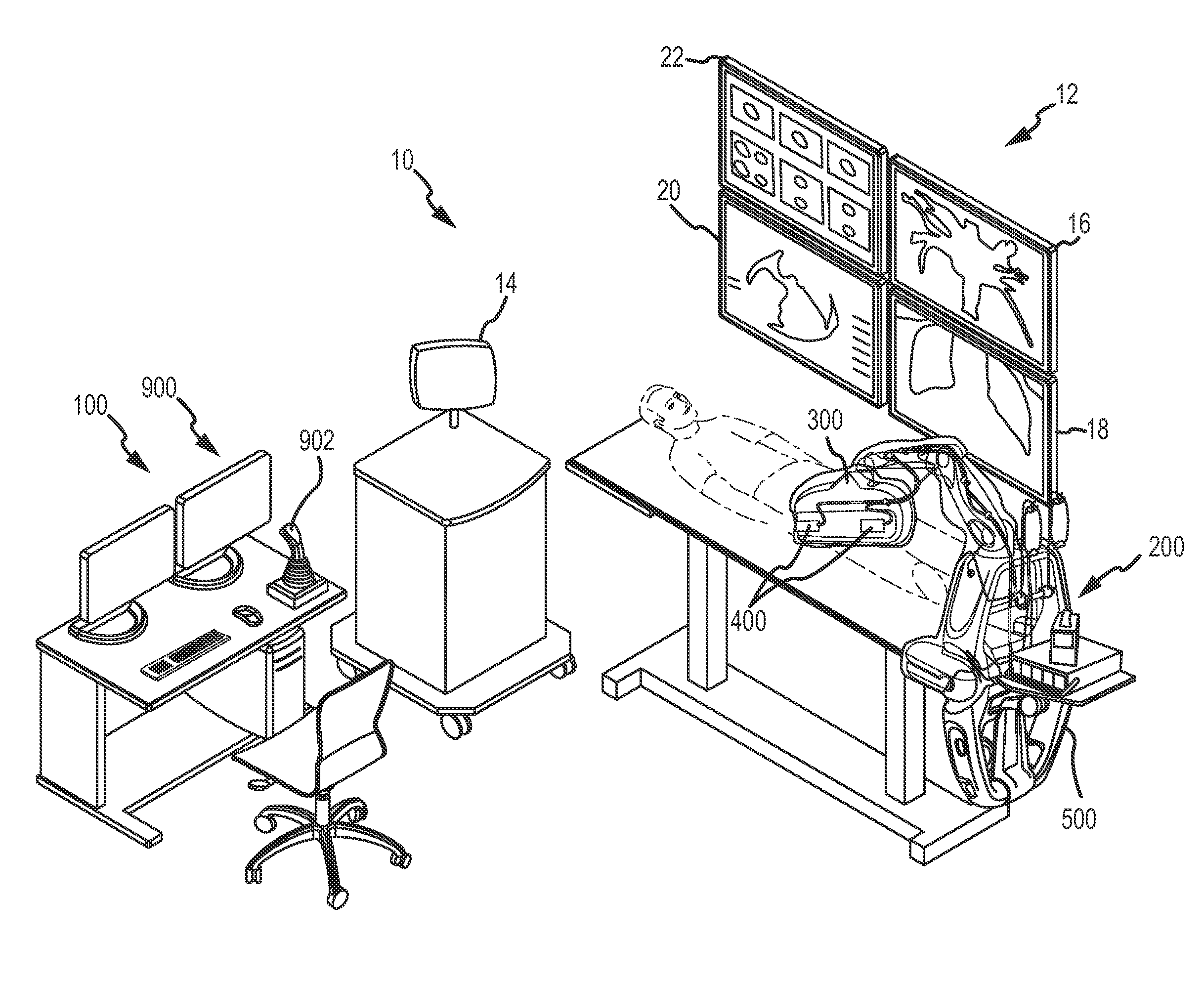
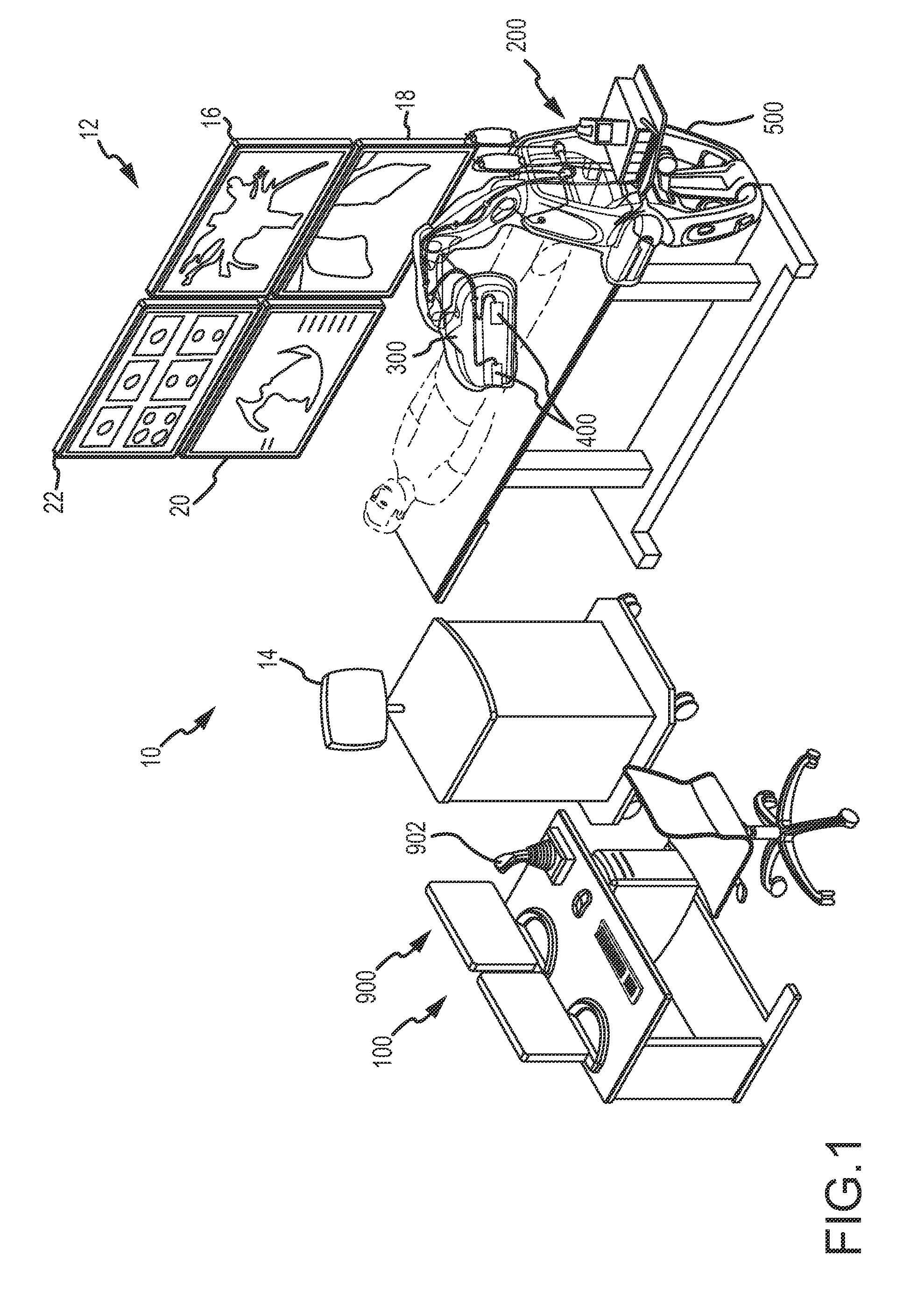
[0030]Referring now to the drawings wherein like reference numerals are used to identify identical components in the various views, an embodiment of robotic catheter system 10 (described in detail in commonly owned and copending application Ser. No. 12 / 347,811 titled “Robotic Catheter System”), also referred to as “the system,” may be likened to “fly by wire” operation for a catheter system. The system may be used, for example, to manipulate the location and orientation of catheters and sheaths in a heart chamber or in another body cavity. As shown in FIG. 1, robotic catheter system 10 may generally incorporate a human input device and control system (referred to as “input control system”) 100, e.g., a joystick and related controls (described briefly below and in detail in commonly owned and copending Application Serial No. PCT / US2009 / 038618 titled “Robotic Catheter System Input Device”), that a user such as an electrophysiologist (EP) may interact with, an electronic control system...


PUM


Abstract

An obstruction detection system for a robotic catheter system including a robotic catheter manipulator assembly including one or more catheter manipulation bases and one or more sheath manipulation bases. Each manipulation base may be generally linearly movable on one or more tracks relative to the robotic catheter manipulator assembly. The obstruction detection system may include one or more obstruction detection sensors disposed on the track or on the manipulation bases to detect an obstruction along a path of motion of one or more manipulation bases. A software system may be provided for monitoring movement of the catheter and sheath manipulation bases, and / or a status of the obstruction detection sensors.

Description

CROSS REFERENCE TO RELATED APPLICATIONS[0001]This application is a continuation-in-part of U.S. non-provisional application Ser. Nos. 12 / 347,811, filed 31 Dec. 2008 (the '811 application), 12 / 347,826, filed 31 Dec. 2008 (the '826 application), 12 / 347,835, filed 31 Dec. 2008 (the '835 application), and 12 / 347,842, filed 31 Dec. 2008 (the '842 application), each of which claim the benefit of U.S. provisional application No. 61 / 099,904, filed 24 Sep. 2008 (the '904 application). The '811, '826, '835, '842 and '904 applications are hereby incorporated by reference as though fully set forth herein.BACKGROUND OF THE INVENTION[0002]a. Field of the Invention[0003]This invention relates to a robotic catheter system and method for automated control of a catheter and related components. In particular, the instant invention relates to a robotic catheter system including a system and method for detection of obstructions that may hinder or otherwise stop movement of catheter and / or sheath manipul...

Claims


Application Information

Patent Timeline
Patent Type & Authority Applications(United States)
IPC IPC(8): A61B19/00
CPCA61B19/2203A61B19/5244A61B2017/00026A61B2019/2211A61B2019/2223A61B2019/2234A61B2017/00477A61B2019/2273A61B2019/2276A61B2019/2292A61B2019/2296A61B2019/464A61B2019/2242A61B2034/742A61B34/20A61B34/71A61B34/37A61B34/76A61B34/77A61B34/30A61B2034/301A61B2034/305A61B2034/741A61B2090/064A61B18/1492A61B2018/00577A61B2034/2055A61B90/06A61B2018/00351A61B2018/00642A61M25/0113A61M25/0147
Inventor AMIRI, ATILASANDHU, KULBIRMARK, BETTYKIRSCHENMAN, MARK B.
Owner ST JUDE MEDICAL ATRIAL FIBRILLATION DIV
Learn More