
Device for controlling traveling of vehicle

Active Publication Date: 2011-07-21
ADVICS CO LTD +1
View PDF14 Cites 43 Cited by
  • Summary
  • Abstract
  • Description
  • Claims
  • Application Information

AI Technical Summary

Benefits of technology

[0006]An object of the present invention is to provide a traveling control apparatus for a vehicle which can reliably evaluate the reliability of curve information obtained from map information of a navigation apparatus, to thereby prevent in-curve speed control from unnecessarily being executed on the basis of curve information whose reliability is low.

Problems solved by technology

Meanwhile, when the actual turning state quantity (e.g., actual lateral acceleration or the like) is small (less than the predetermined value), it can be considered that the possibility of the vehicle actually traveling within the curve is low, and the reliability of the curve information is low.

Method used


Image

  • Device for controlling traveling of vehicle
  • Device for controlling traveling of vehicle
  • Device for controlling traveling of vehicle

Examples


first embodiment

(Configuration)

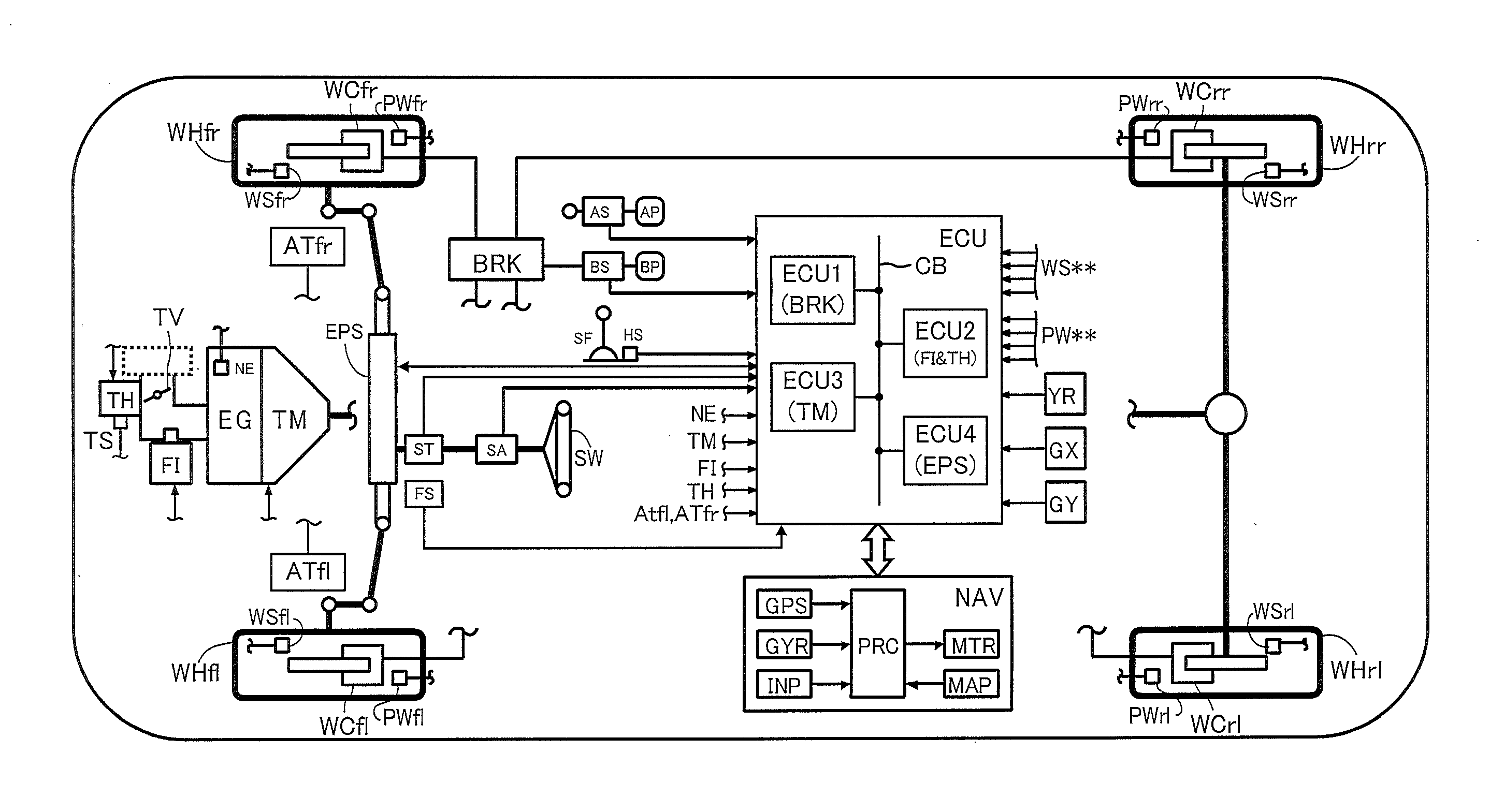
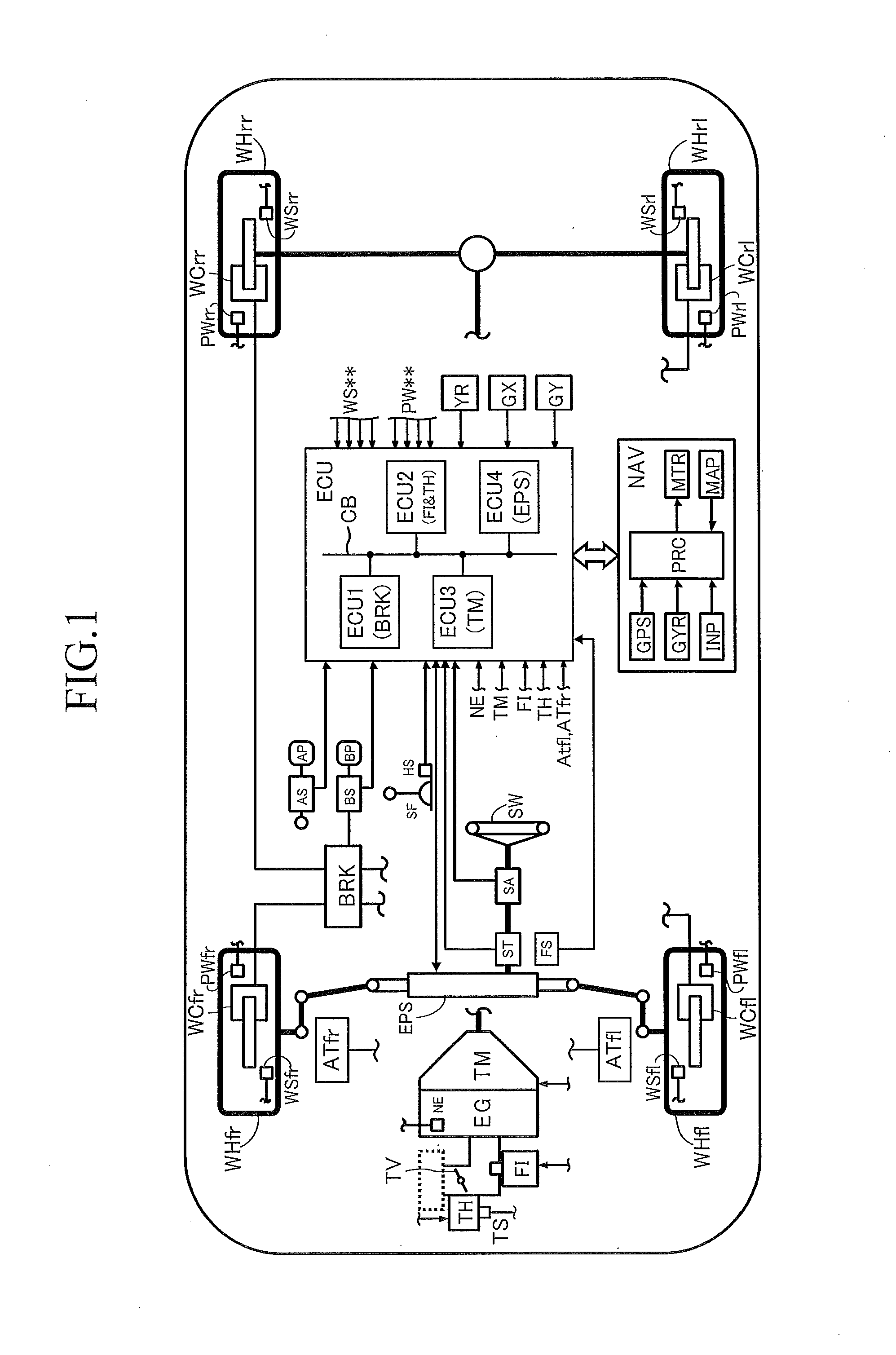
[0079]FIG. 1 schematically shows the structure of a vehicle on which the traveling control apparatus according to a first embodiment of the present invention (hereinafter referred to as the “present apparatus”) is mounted. The present apparatus includes an engine EG, which is a power source of the vehicle, an automatic transmission TM, a brake actuator BRK, an electronic control unit ECU, and a navigation apparatus NAV.

[0080]For example, the engine EG is an internal combustion engine. A throttle actuator TH adjusts the opening of a throttle valve TV in response to operation of an accelerator pedal (accelerating operation member) AP by a driver. A fuel injection actuator FI (injector) injects fuel in an amount in proportion to the intake air amount adjusted in accordance with the opening of the throttle valve TV. Thus, the engine EG outputs an output torque corresponding to the amount of operation of the accelerator pedal AP by the driver.

[0081]The automatic transmissi...

second embodiment

[0239]Next, a traveling control apparatus and a curve information reliability evaluation apparatus according to a second embodiment of the present invention (hereinafter may be referred to as the “present apparatus”) will be described. Since the mechanical configuration of the second embodiment is identical with that of the first embodiment, its detailed description is omitted here.

(Outline of Evaluation of the Reliability of the Curve Information by the Present Apparatus)

[0240]Hereinafter, a method for computing the reliability Sq of the curve information by the present apparatus will be described with reference to FIG. 20.

[0241]First, curve information acquisition means C1 acquires information Rc, Pc (a position Pc and a curve curvature radius Rc at that position) of a curve ahead of the vehicle. The curve information Rc, Pc is stored in the map information database of the storage section MAP. The curve information includes pieces of information each representing a position Pc (e....


PUM


Abstract

After a vehicle has entered a curve, a deviation (Sch) between a target turning state quantity Td and an actual turning state quantity Ta is computed. In a stage in which Sch does not reach a predetermined value after the vehicle has entered the curve, the possibility of the vehicle traveling in the curve is judged to be low, and the reliability of the curve information Rc, Pc is judged to be low. In this case, a determination for prohibiting execution of control (So=0) is made. In a stage after Sch has reached the predetermined value, the possibility of the vehicle traveling in the curve is judged to be high, and the reliability of the curve information Rc, Pc is judged to be high. In this case, a determination for permitting execution of the control (So=1) is made. Deceleration control is started and executed only when a control start condition is satisfied, and the determination for permission is made. Accordingly, even when the control start condition is satisfied, the deceleration control is not started, if the prohibition determination is made. Thus, the reliability of the curve information based on map information on the vehicle is evaluated reliably, and the deceleration control within the curve can be prevented from being unnecessarily executed on the basis of curve information whose reliability is low.

Description

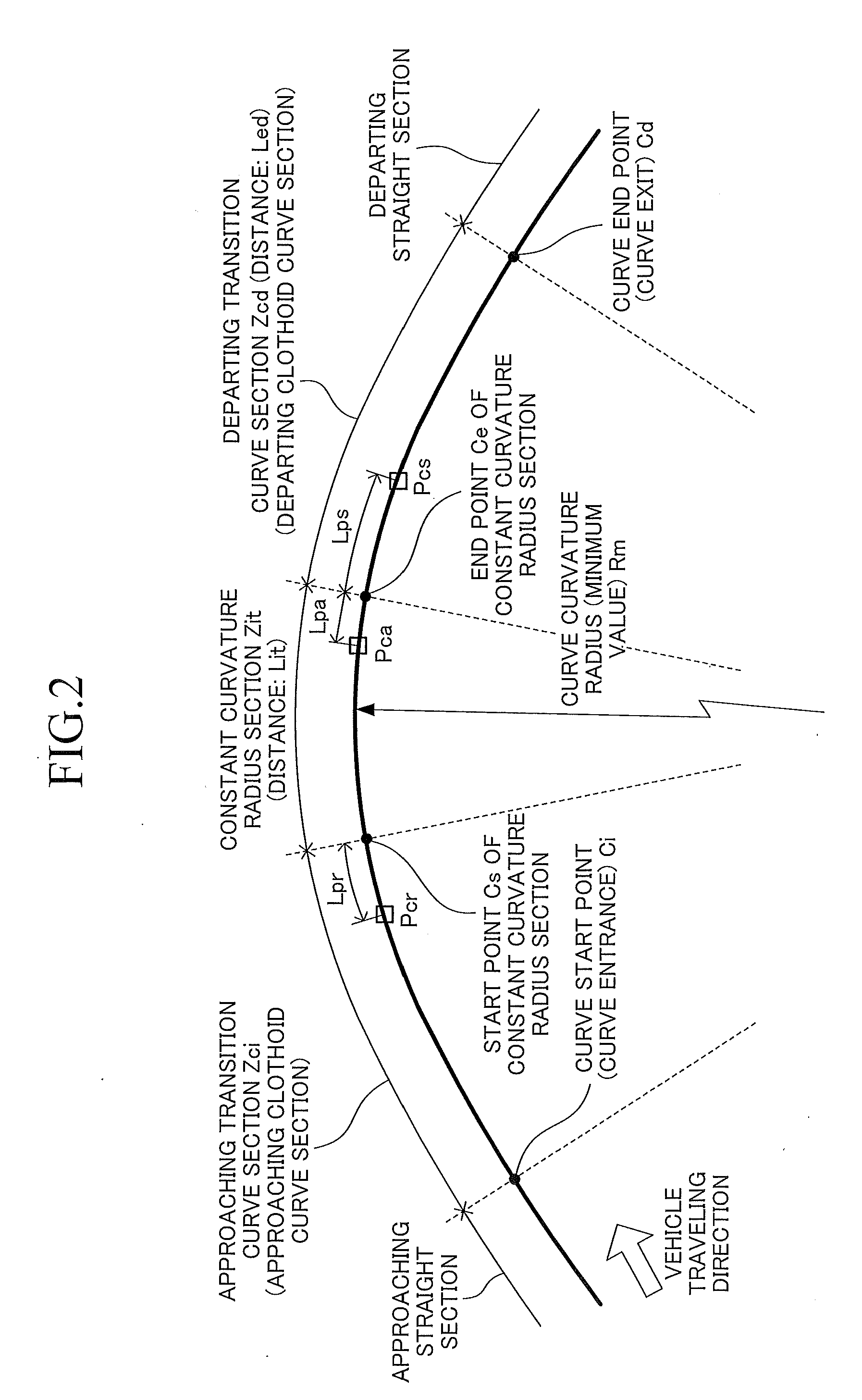
TECHNICAL FIELD[0001]The present invention relates to a traveling control apparatus for a vehicle which performs deceleration control on the basis of curve information when the vehicle travels along a curve.BACKGROUND ART[0002]Conventionally, there has been widely known a technique for performing speed control when a vehicle passes through a curve, on the basis of curve information obtained from map information stored in a navigation apparatus mounted on the vehicle. The curve information (the shape of the curve) obtained from the map information on the vehicle may differ from the actual shape of the curve, for example, in the case where a road has been renovated after the map information (database) had been created. That is, the reliability of the map information (curve information) on the vehicle is not high at all times.[0003]Japanese Patent Application Laid-Open (kokai) No. H11-211492 describes a technique for acquiring final road information from the result of comparison betwee...

Claims


Application Information

Patent Timeline
IPC IPC(8): G06F7/00B60T8/1755B60T7/12B60W30/02B60W40/06
CPCB60T7/12B60T8/1755B60W40/076B60W30/045B60W40/072B60T2201/16B60K31/0066B60K31/0075B60K31/0083B60W30/02B60W30/14B60W30/143B60W30/18145B60W2520/125B60W2520/14B60W2540/18B60W2552/30G01C21/28
Inventor YASUI, YOSHIYUKISUZUKI, MOTOSHIKOTO, HIDEAKINORO, KAZUTAKEKODAMA, HIROYUKITANAKA, MANABUMIYAJIMA, YAKAYUKI
Owner ADVICS CO LTD
Learn More