Method and device for fault location of series-compensated transmission line

a transmission line and fault location technology, applied in the field of electric power distribution systems, can solve problems such as faults on series-compensated transmission lines, and achieve the effect of accurate fault location and accurate fault location algorithm

Active Publication Date: 2011-07-21
HITACHI ENERGY SWITZERLAND AG
View PDF5 Cites 28 Cited by
  • Summary
  • Abstract
  • Description
  • Claims
  • Application Information

AI Technical Summary

Benefits of technology

[0012]It is an object of the invention to provide an accurate fault location algorithm for series-compensated lines. In particular, it is an objec

Problems solved by technology

However, to locate faults on series-compensated transmission lines offers several challenges.
For example, if the apparent impedance is used as a measure

Method used


Image

  • Method and device for fault location of series-compensated transmission line
  • Method and device for fault location of series-compensated transmission line
  • Method and device for fault location of series-compensated transmission line

Examples


Embodiment Construction

[0023]The same reference numerals are used throughout the figures and description for denoting same or corresponding parts.

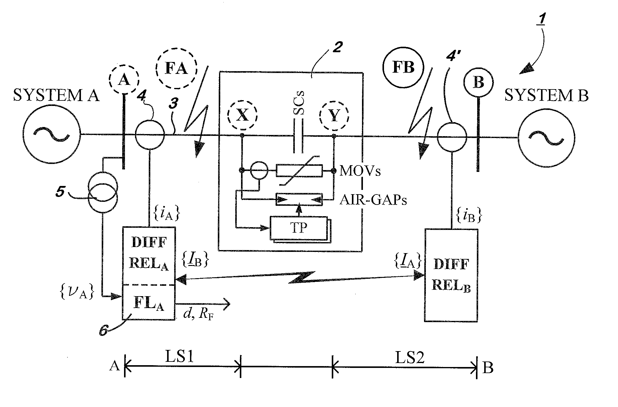
[0024]The developed fault location algorithm in accordance with the present invention is suitable for application to a transmission line, or distribution line, compensated with a capacitor bank, for example a three-phase bank of fixed series capacitors equipped with MOVs (metal oxide varistors), in the following abbreviated SC&MOV, for overvoltage protection.

[0025]FIG. 1 illustrates the transmission line system 1 wherein the two-terminal transmission line 3 is series-compensated by means of a compensating bank, in the following denoted capacitor bank 2. A fault locator 6 is installed at the transmission line end A (or terminal A). The fault locator 6 is provided with current and voltage measurement values from the transmission line 3. Current measurements are provided from both line ends A, B and voltage measurements are provided from one end (the local end, i.e...


PUM


Abstract

A transmission line system, a device for fault protection and computer programs, and a method for locating a fault in a series-compensated two-terminal power transmission line including a compensating bank for providing series-compensation to the transmission line. Different subroutines are utilized for locating faults on line segments from the first terminal to the compensating bank and line segments from the second terminal to the compensating bank. A selection is then made in order to determine a valid result. The subroutines utilize three phase currents synchronized measurements from both terminals and a three phase voltage measurements from one terminal for determining the respective per unit distance to a fault.

Description

CROSS-REFERENCE TO RELATED APPLICATIONS[0001]The present application is a continuation of pending International patent application PCT / EP2008 / 059424 filed on Jul. 18, 2008 which designates the United States, the content of which is incorporated herein by reference.FIELD OF THE INVENTION[0002]The present invention relates generally to the field of electrical power distribution systems, and in particular to methods for protection and to protection equipment within such systems.BACKGROUND OF THE INVENTION[0003]An electrical transmission system comprises protection means arranged to protect, monitor and control the functioning of devices forming part of the transmission system. The protection systems detect, among other things, short-circuits, over-currents and over-voltages in the transmission lines, transformers and other parts of the power transmission system.[0004]Protection equipment is used throughout the electrical power transmission system for providing such protection and contr...

Claims


Application Information

Patent Timeline
IPC IPC(8): G01R31/08G06F19/00
CPCG01R31/085G01R31/088G01R31/08
Inventor SAHA, MURARI
Owner HITACHI ENERGY SWITZERLAND AG
Why Eureka
Try Eureka