Surface covering system

a technology of surface covering and surface covering, which is applied in the direction of floor covering, construction materials, building components, etc., can solve the problems of surface covering, gaps formed, and further demands

Inactive Publication Date: 2011-07-28
GIANOLI GABRIELLA
View PDF16 Cites 17 Cited by
  • Summary
  • Abstract
  • Description
  • Claims
  • Application Information

AI Technical Summary

Benefits of technology

to provide a surface covering system, which avoids the above-described disadvantages of known surface covering systems at least extensively. In particular, the surface covering system should be constructed in a modular manner and at the same time provide a seal that is aesthetically pleasing yet technically improved.

Problems solved by technology

However, apart from the mechanical demands made on these types of surface covering systems, in many cases further demands are made.
However, in practice these known devices and methods have a multitude of disadvantages, which are not tolerable in every case and which sometimes lead to unsatisfactory results in the surface covering.
A change in the dimension of the pieces over the period of use, for example by absorbing moisture or the timber “moving”, can also lead to these types of gaps being formed.
However, the effect of said gaps is that moisture is able to pass between the sealing profile and the piece to the supporting frame lying underneath and / or to the surface to be covered lying underneath.
A similar problem is also presented with systems like the system described in CH 508 792, where two seals of adjacent modules are pressed onto each other.
Another disadvantage of known two-part sealing systems, such as, for example, the sealing system described in CH 508 792, is of both an esthetic and a technical nature.
This non-uniformity is not only undesirable esthetically, but could even result in leakages in the region of said edge on account of the curvature and of the stresses occurring at that location, in particular if the sealing material becomes increasingly brittle due to age.

Method used


Image

  • Surface covering system
  • Surface covering system
  • Surface covering system

Examples


Embodiment Construction

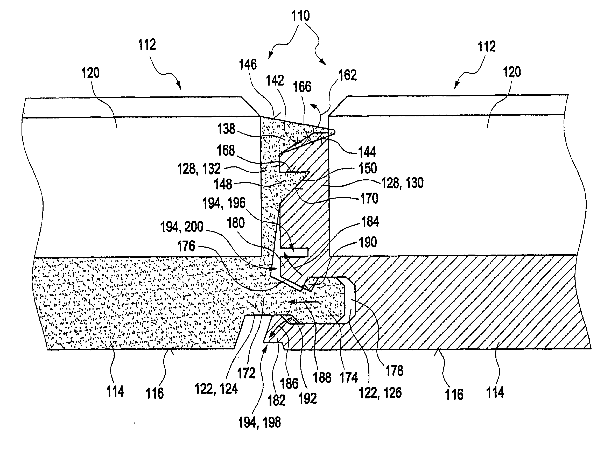
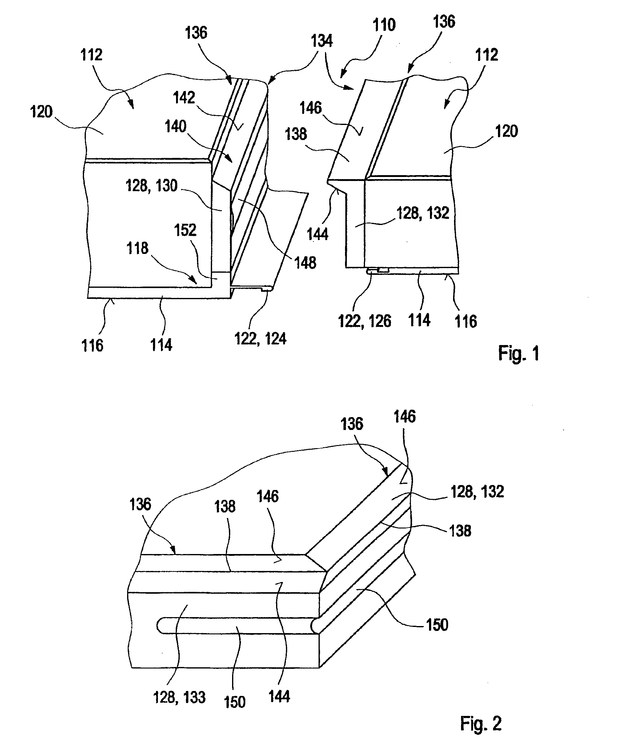
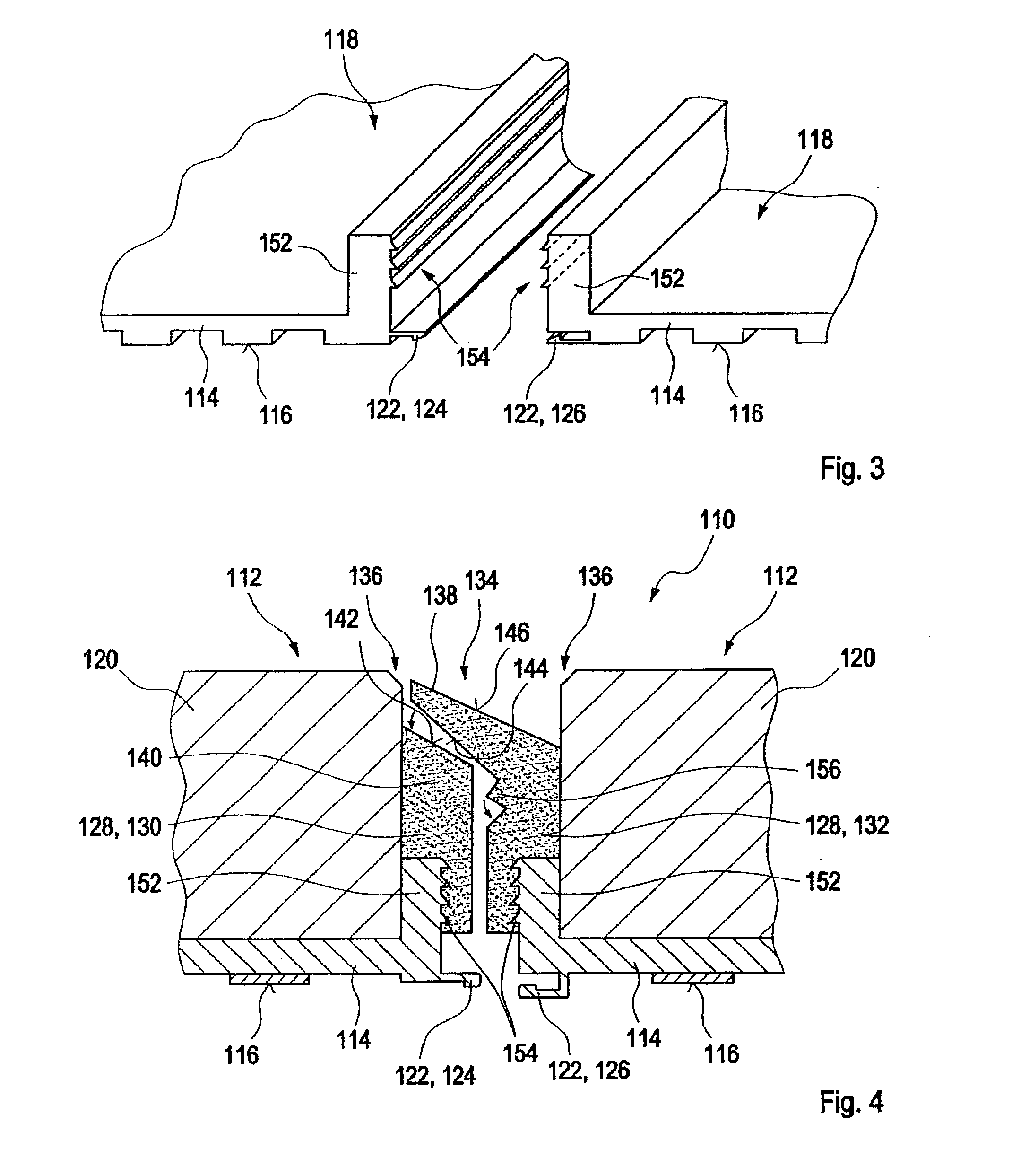
FIG. 1 shows a perspective representation of a first exemplary embodiment of a surface covering system 110 as claimed in the invention. In this case, cutouts of two covering modules 112 that interact in a complementary manner are represented not to scale and not to the correct scale one relative to the other. Said covering modules 112, when laid, are joined together, where applicable in common with further covering modules 112, to form the surface covering system 110.

The covering modules 112 include in each case a frame 114. Said frame 114 can be shaped, for example, as a plastics material frame and presents at least one supporting surface 116 for contact with the surface to be covered. The frame 114 can be shaped, for example, as a grid-shaped frame and in the exemplary embodiment shown comprises, for example, an indentation 118.

Covering materials 120 are inserted in each case into the indentation 118 of the frame 114. Said covering materials 120 are represented in the exemplary em...


PUM

PropertyMeasurementUnit
angleaaaaaaaaaa
angleaaaaaaaaaa
angleaaaaaaaaaa

Abstract

A surface covering system for covering surfaces with a covering material, particularly for covering wall surfaces or floor surfaces with tile material. The surface covering system includes at least two covering modules, which can be placed on the surface so as to adjoin each other. A first covering module has at least one first sealing profile, and a second covering profile has at least one second sealing profile. The sealing profiles are designed to engage each other in a positioned state of the covering modules and form a common seal.

Description

BACKGROUND OF THE INVENTION1. Field of the InventionThe invention relates to a surface covering system for covering surfaces with a covering material and to a covering module and a frame for use in this type of surface covering system. These types of surface covering systems, covering modules and frames are used to cover almost any surface, for example wall surfaces, floor surfaces, ornate surfaces or the like, in particular in the area of construction engineering. In principle, however, other applications are also possible.2. Description of Related ArtNumerous surface covering systems, designed according to different criteria, are known, in particular in the area of construction engineering. These types of surface covering systems, as are also proposed within the framework of the present invention, are used, for example, to cover wall surfaces, floor surfaces or ceiling surfaces with a covering material. This covering material can include different materials, for example metal mate...

Claims


Application Information

Patent Timeline
Patent Type & Authority Applications(United States)
IPC IPC(8): E04C2/38E04C2/20
CPCE04B1/6129E04F13/0889E04F15/02005E04F2201/041E04F2201/0115E04F2201/0153E04F15/04E04F15/02011E04F15/02016
Inventor PAETROW, JORGPALGAN, MARIUSZ
Owner GIANOLI GABRIELLA
Why Eureka
Try Eureka