Particle separator and debris control system

a technology of particle separator and control system, which is applied in the direction of separation process, machine/engine, liquid fuel engine, etc., can solve the problems of large amount of dust and debris, and large amount of debris on the landing and taking off from unpaved areas

Active Publication Date: 2011-07-28
RAYTHEON TECH CORP
View PDF12 Cites 35 Cited by
  • Summary
  • Abstract
  • Description
  • Claims
  • Application Information

AI Technical Summary

Problems solved by technology

Low-altitude operation poses operational difficulties for gas turbine engines not always presented at higher altitudes.
For instance, landing and taking-off from unpaved areas can “kick up” large amounts of dust and debris.
As such, gas turbine engines of rotorcraft operating at low altitudes are often exposed to ambient air that contains a significant amount of debris, typically consisting of large amounts of small, airborne particles or dust.
Debris ingested by gas turbine engines is problematic, and can cause erosion and other damage to components of the engine.
Such damage can cause engine performance to deteriorate, and can make engine repairs necessary.
For example. gas turbine engines contain airfoils having thin edges and tips that are highly sensitive to erosion, and any erosion damage to those areas can significantly impair the efficiency and effectiveness of the airfoil.
A problem with these systems is that the mechanical power diverted to the IPS system produces a parasi

Method used


Image

  • Particle separator and debris control system
  • Particle separator and debris control system
  • Particle separator and debris control system

Examples


Embodiment Construction

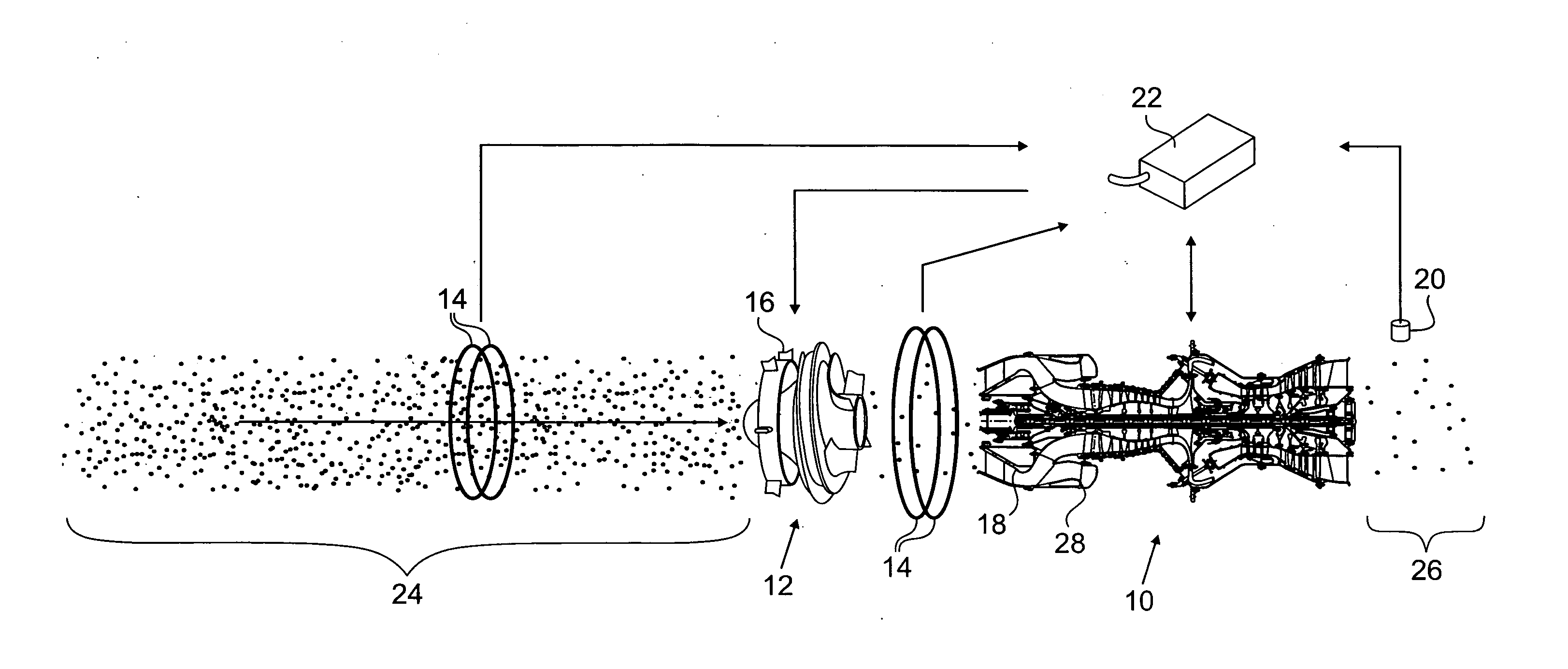
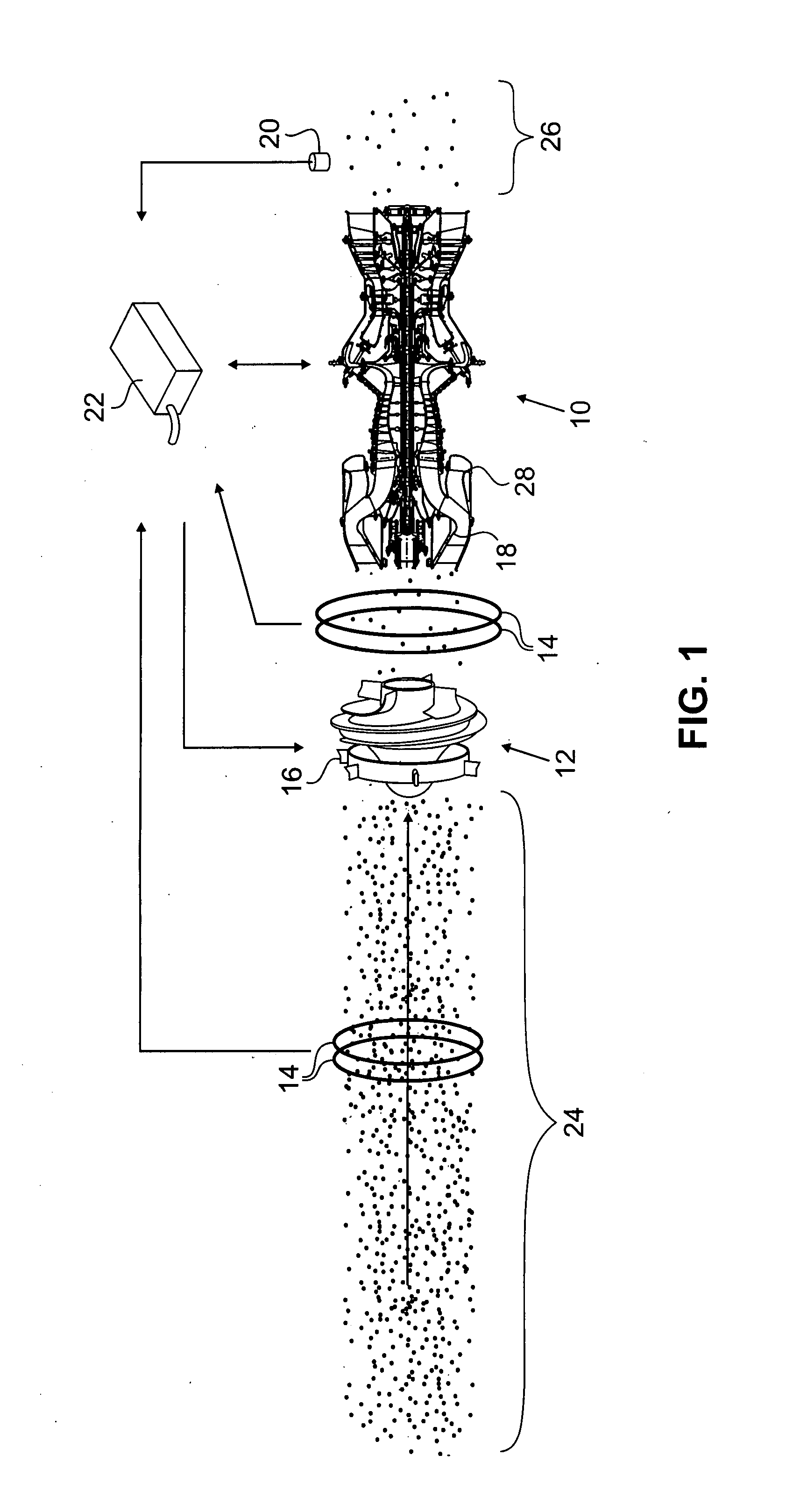
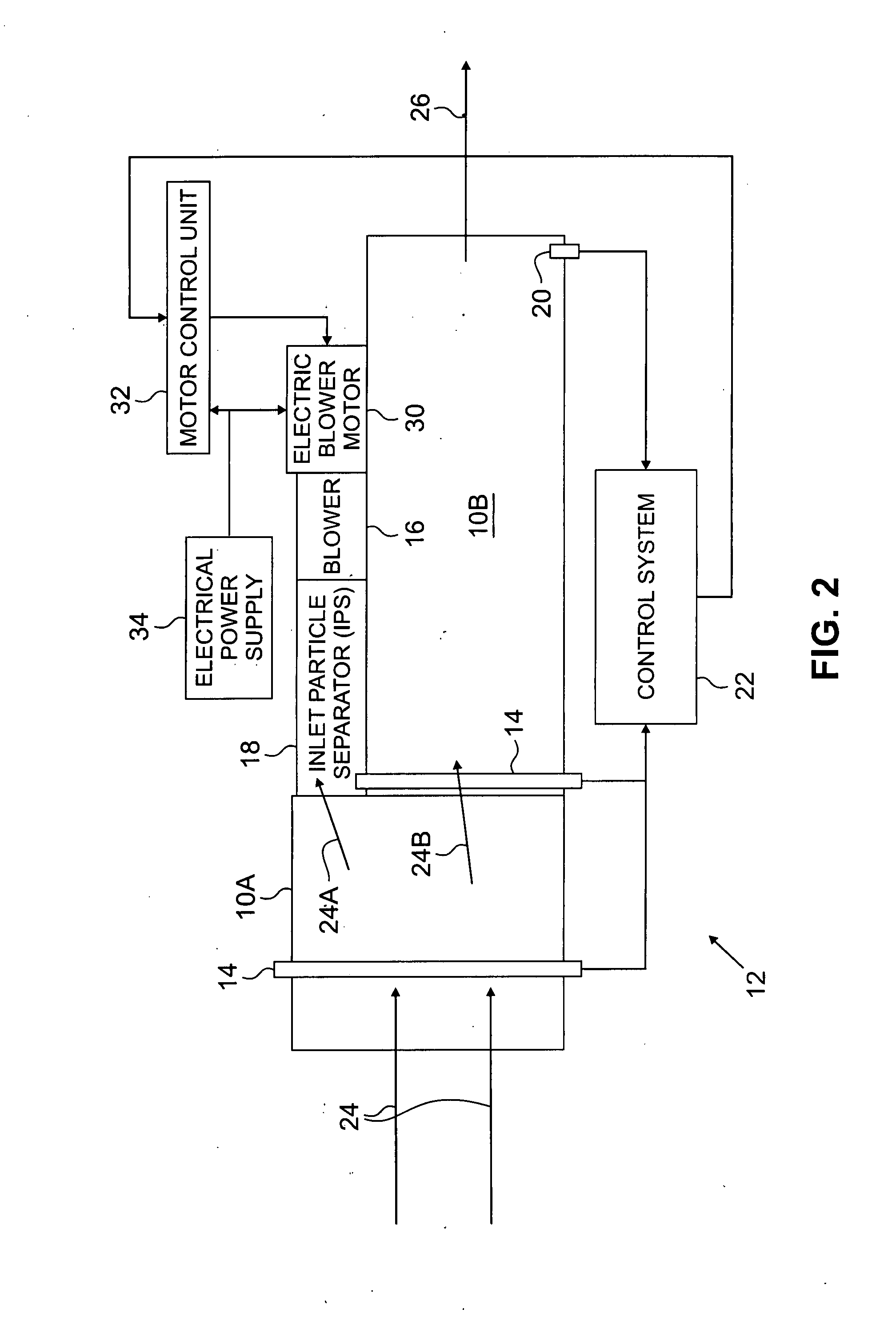
[0008]In general, the present invention provides a debris control system having a blower that can be powered at selected speed and power settings as a function of the distribution of debris present in ambient air entering a gas turbine engine. The blower can thus be turned “on” or “off” on demand, and, when turned on, operated at speed and power settings that are dynamically matched to desired particle separation performance characteristics in real time. This provides efficient operation of the debris control system with reduced power consumption. As used herein, the term “debris” refers generally to any kind of airborne particulate or foreign object matter present in ambient air that can enter a gas turbine engine.

[0009]FIG. 1 is an exploded schematic view of a gas turbine engine 10 having a debris control system 12 that includes an inlet debris monitoring system (IDMS) 14, a blower 16, a particle separator “ramp”18, an exhaust debris monitoring system (EDMS) 20, and a control syst...


PUM

PropertyMeasurementUnit
Speedaaaaaaaaaa
Shapeaaaaaaaaaa

Abstract

A gas turbine engine system includes an air inlet, an inlet particle separator located at the air inlet and having a blower selectively driven by a variable output motor, and a controller for dynamically controlling the variable output motor that selectively drives the blower of the inlet particle separator.

Description

BACKGROUND OF THE INVENTION[0001]The present invention relates to particle separators and debris control systems for use with gas turbine engines.[0002]Rotorcraft (e.g., helicopters) that use gas turbine engines can operate at a variety of altitudes, and can generally operate at relatively lower altitudes than most fixed-wing aircraft. Low-altitude operation poses operational difficulties for gas turbine engines not always presented at higher altitudes. For instance, landing and taking-off from unpaved areas can “kick up” large amounts of dust and debris. As such, gas turbine engines of rotorcraft operating at low altitudes are often exposed to ambient air that contains a significant amount of debris, typically consisting of large amounts of small, airborne particles or dust. Debris ingested by gas turbine engines is problematic, and can cause erosion and other damage to components of the engine. Such damage can cause engine performance to deteriorate, and can make engine repairs ne...

Claims


Application Information

Patent Timeline
IPC IPC(8): F02G3/00
CPCB01D45/14B64D33/02B64D2033/0246F05D2270/30F02C7/057F04D29/701F05D2270/01F02C7/052
Inventor RAJAMANI, RAVIAGRAWAL, RAJENDRA K.WOOD, COY BRUCE
Owner RAYTHEON TECH CORP
Why Eureka
Try Eureka