Multilayered ceramic component and manufacturing method thereof

a multi-layered ceramic and manufacturing method technology, applied in the direction of transformer/inductance magnetic core, inductance, magnetic body, etc., can solve the problems of reducing the reliability of laminated ceramic components, reducing reliability, and reducing the reliability of silver in borosilicate glass, so as to suppress the migration of silver and high reliability

Active Publication Date: 2011-07-28
PANASONIC CORP
View PDF3 Cites 34 Cited by
  • Summary
  • Abstract
  • Description
  • Claims
  • Application Information

AI Technical Summary

Benefits of technology

[0008]The present invention offers a highly-reliable laminated ceramic component that suppresses migration of silver. The laminated ceramic component of the present invention includes a ferrite magnetic layer and a glass ceramic layer made chiefly of borosilicate glass. The glass ceramic layer is laminated with the ferrite magnetic layer and has a silver inner conductor embedded inside. A microscopic region where aluminum and silver coexist is dispersed in the glass ceramic layer. This laminated ceramic component is manufactured in the following way. First, a glass ceramic green sheet is made by mixing borosilicate glass powder, crystalline silica, and hydrated alumina powder. The mixing ratio of hydrated alumina is not less than 0.5 weight percent and not greater than 4.5 weight percent in the glass ceramic green sheet. Next, the silver inner conductor is formed in this glass ceramic green sheet. A ferrite green sheet and the glass ceramic green sheet are then laminated to form a laminated body. This laminated body is sintered at a temperature not higher than the melting point of silver.

Problems solved by technology

However, silver is liable to spread across a wide area in borosilicate glass if conventional borosilicate glass is used as a low-dielectric material for a glass ceramic layer.
This leads to defects, including short-circuiting, that cause reduced reliability.
This significantly reduces the reliability of the laminated ceramic component.

Method used


Image

  • Multilayered ceramic component and manufacturing method thereof
  • Multilayered ceramic component and manufacturing method thereof
  • Multilayered ceramic component and manufacturing method thereof

Examples


Embodiment Construction

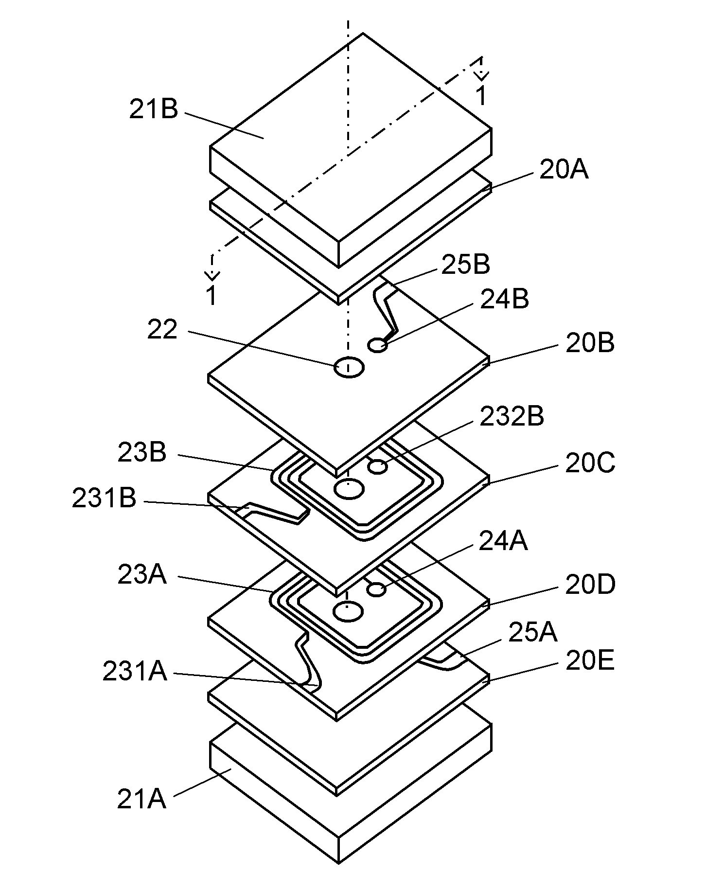
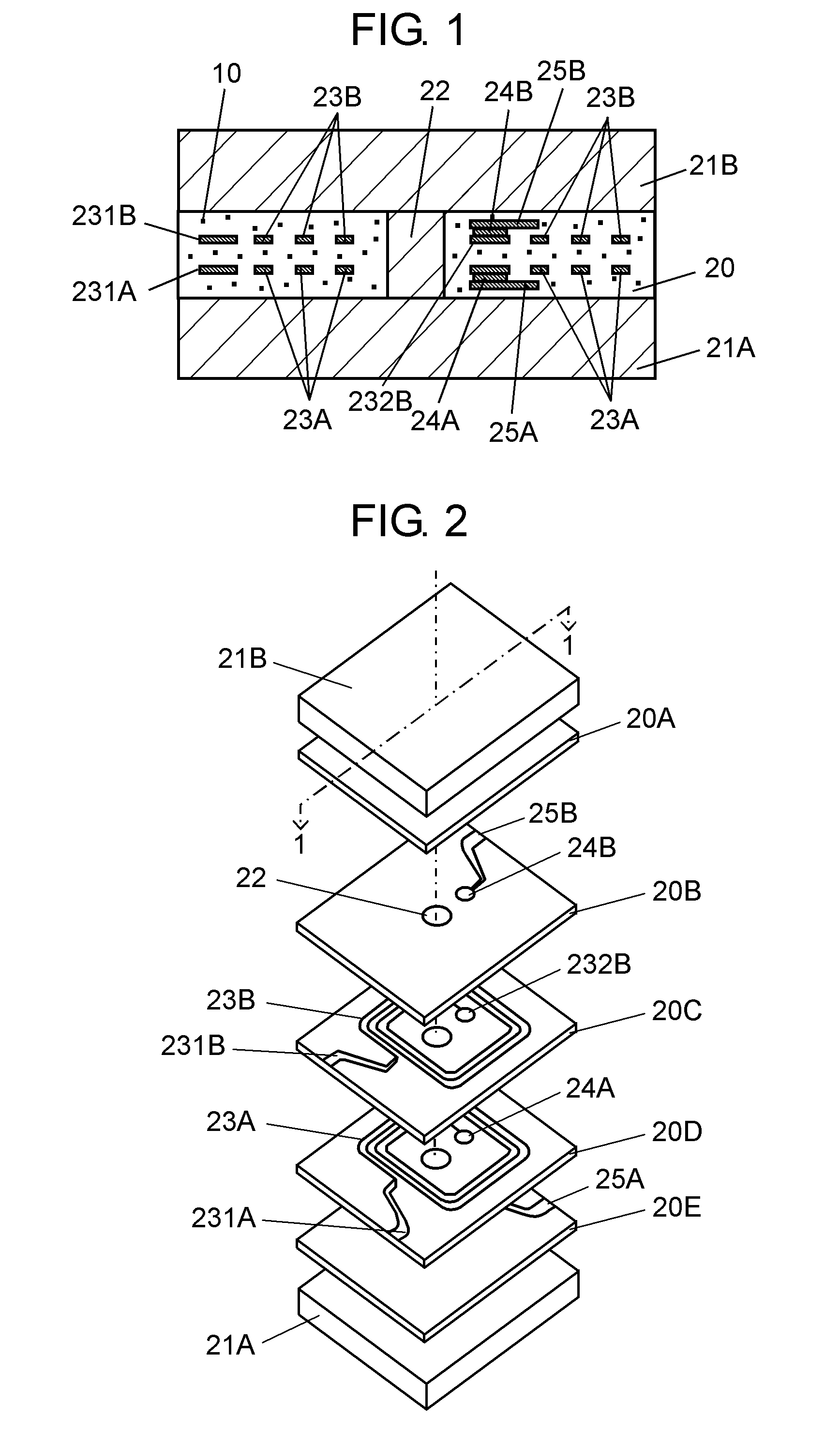
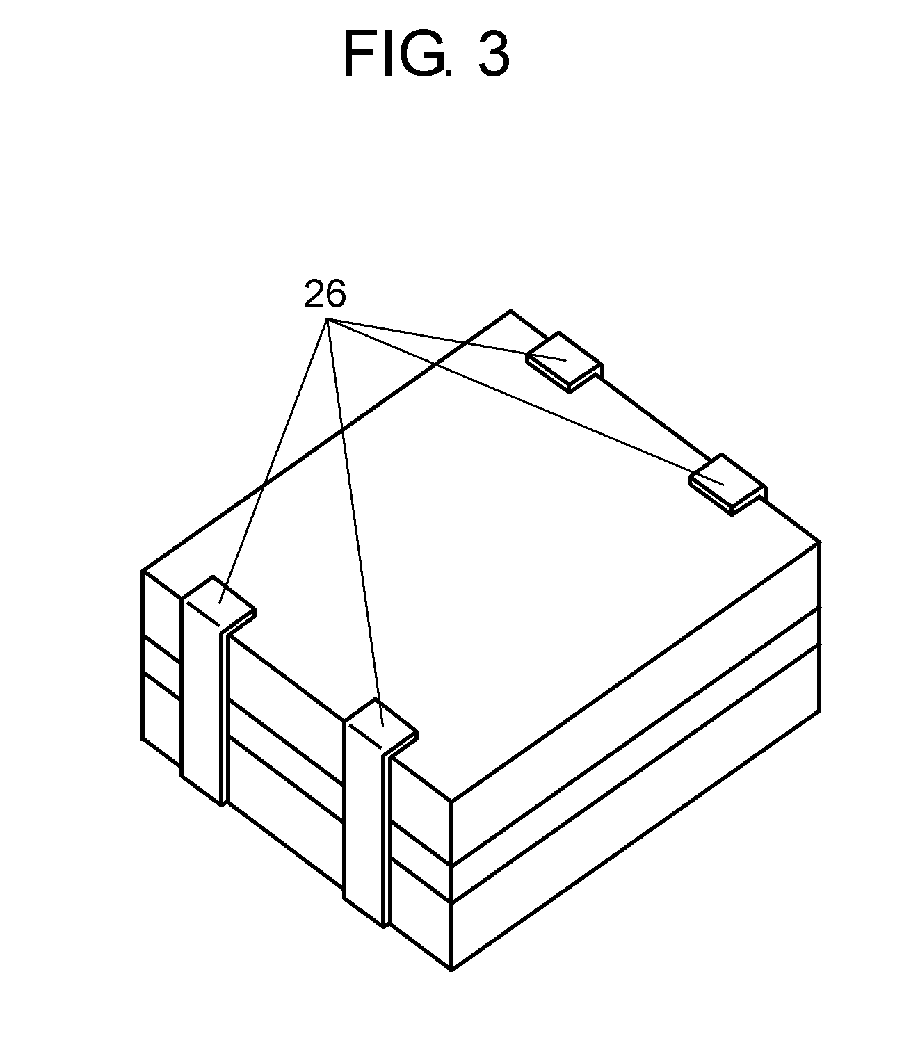
[0013]A laminated ceramic component of the present invention is described below using an example of a common-mode noise filter that is obtained by sintering simultaneously a ferrite green sheet and a glass ceramic green sheet. FIG. 1 is a sectional view of the laminated ceramic component, FIG. 2 is an exploded perspective view of this laminated ceramic component, and FIG. 3 is an external view of this laminated ceramic component. FIG. 1 is the sectional view taken along line 1-1 in FIG. 2.

[0014]As shown in FIG. 1, the laminated ceramic component includes glass ceramic layer 20 made chiefly of borosilicate glass, ferrite magnetic layers 21A and 21B, ferrite via 22, and silver (Ag) flat coils 23A and 23B. Microscopic region 10 where aluminum (Al) and Ag coexist is dispersed in glass ceramic layer 20. Ferrite magnetic layers 21A and 21B sandwich glass ceramic layer 20.

[0015]As shown in FIGS. 1 and 2, flat coil 23A is formed on layer 20D, and lead wire 25A is formed on layer 20E. One en...


PUM

PropertyMeasurementUnit
melting pointaaaaaaaaaa
weight percentaaaaaaaaaa

Abstract

A laminated ceramic component includes a ferrite magnetic layer and a glass ceramic layer made chiefly of borosilicate glass. The glass ceramic layer is laminated with the ferrite magnetic layer, and has an Ag inner conductor embedded inside. A microscopic region where aluminum and silver coexist is dispersed in the glass ceramic layer.

Description

TECHNICAL FIELD[0001]The present invention relates to laminated ceramic components employed in a range of electronic devices, and more particularly to laminated ceramic components that can be sintered at low temperatures.BACKGROUND ART[0002]In response to the need for electronic devices to cope with an increasing volume of information at ever higher speeds, laminated ceramic components installed in electronic devices need to support higher frequencies. An effective way of achieving this is to reduce the stray capacitance of circuit patterns in laminated ceramic components. An insulating material used in laminated ceramic components thus needs to have a low dielectric constant.[0003]In this type of laminated ceramic component, silver, which has high conductivity, is often used for the circuit patterns formed inside, to reduce electric resistance inside the circuit. Therefore, the insulating material with low dielectric constant needs to be sintered and densified at around 900° C., no...

Claims


Application Information

Patent Timeline
Patent Type & Authority Applications(United States)
IPC IPC(8): H01F27/24C03B29/00
CPCC03C14/004C03C2214/08H01F1/344H01F2017/0066H01F41/046H01F41/16H01F17/0013C04B35/16H01F17/04
Inventor INUDUKA, TSUTOMUMOTOMITSU, HIRONORI
Owner PANASONIC CORP
Why Eureka
Try Eureka