Display device and display driving method

a technology of display device and driving method, applied in the field of display, can solve the problems of difficulty in realizing a large-scale, high-definition display, simple matrix system, etc., and achieve the effect of eliminating streaks and reducing illumination differences

Active Publication Date: 2011-07-28
JOLED INC
View PDF17 Cites 7 Cited by
  • Summary
  • Abstract
  • Description
  • Claims
  • Application Information

AI Technical Summary

Benefits of technology

[0032]In contrast, in the embodiments of the present invention, the writing order of the video signal voltages for the respective lines in a unit is inverted on a unit-by-unit basis, and thereby the luminance difference at the boundary between units can be cancelled. That is, streak-manner displaying on the screen can be eliminated.

Problems solved by technology

The simple-matrix system has problems of e.g. difficulty in realization of a large-scale, high-definition display although having a simple configuration.

Method used


Image

  • Display device and display driving method
  • Display device and display driving method
  • Display device and display driving method

Examples


Embodiment Construction

[0044]An embodiment of the present invention will be described below in the following order.

[1. Configurations of Display Device and Pixel Circuit]

[2. Pixel Circuit Operation Considered in Process of Reaching the Present Invention: Divided Threshold Correction]

[0045][3. Pixel Circuit Operation Considered in Process of Reaching the Present Invention: STC driving]

[4. Pixel Circuit Operation of Embodiment]

[1. Configurations of Display Device and Pixel Circuit]

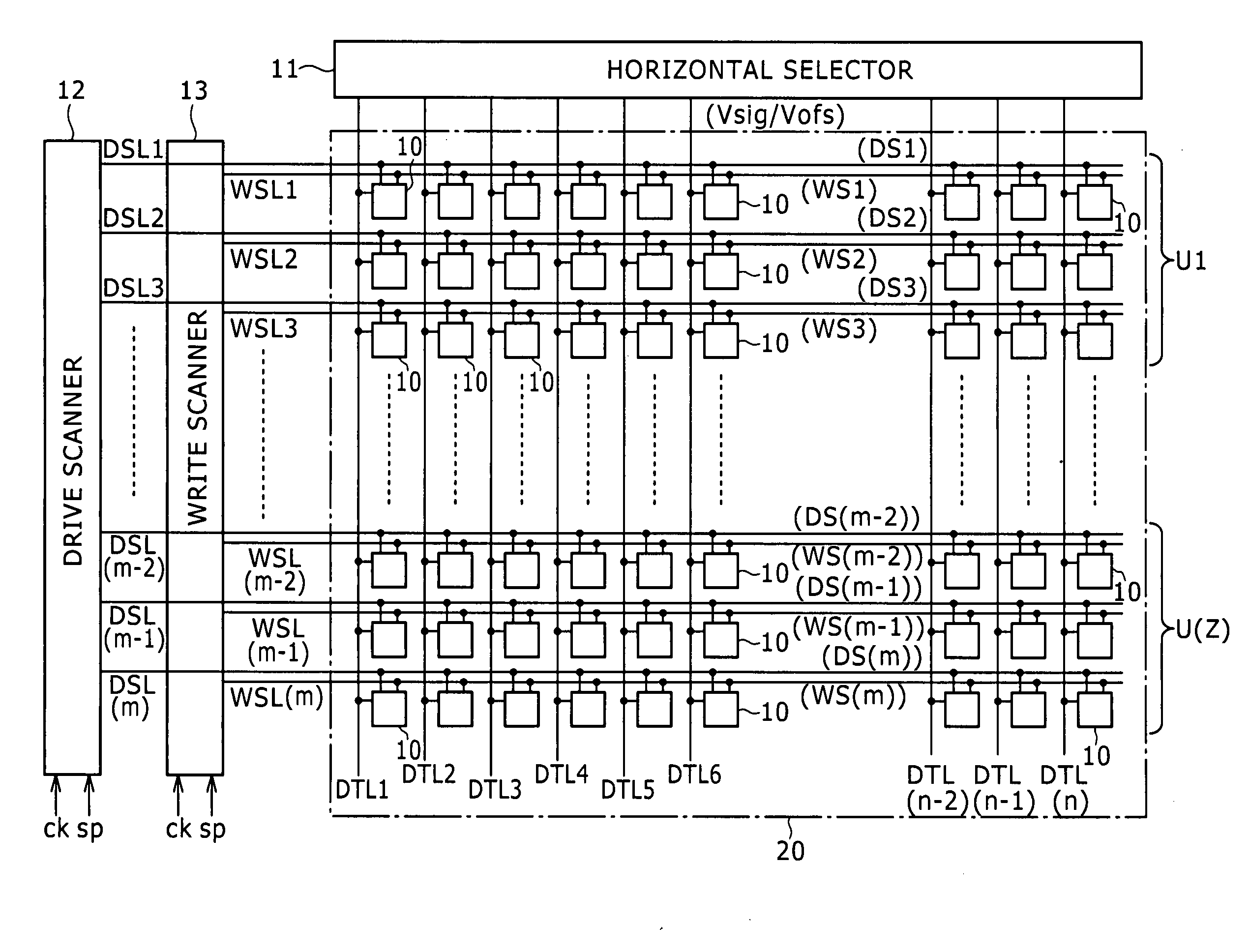
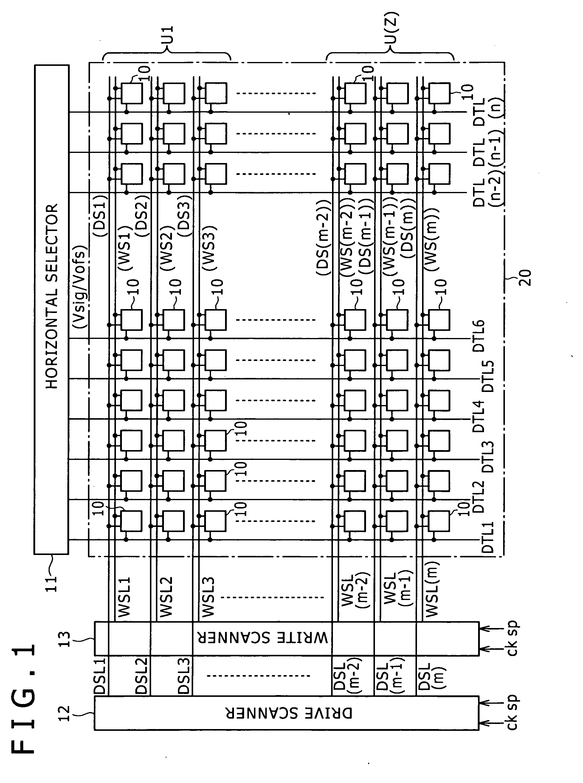
[0046]FIG. 1 shows the configuration of an organic EL display device according to the embodiment.

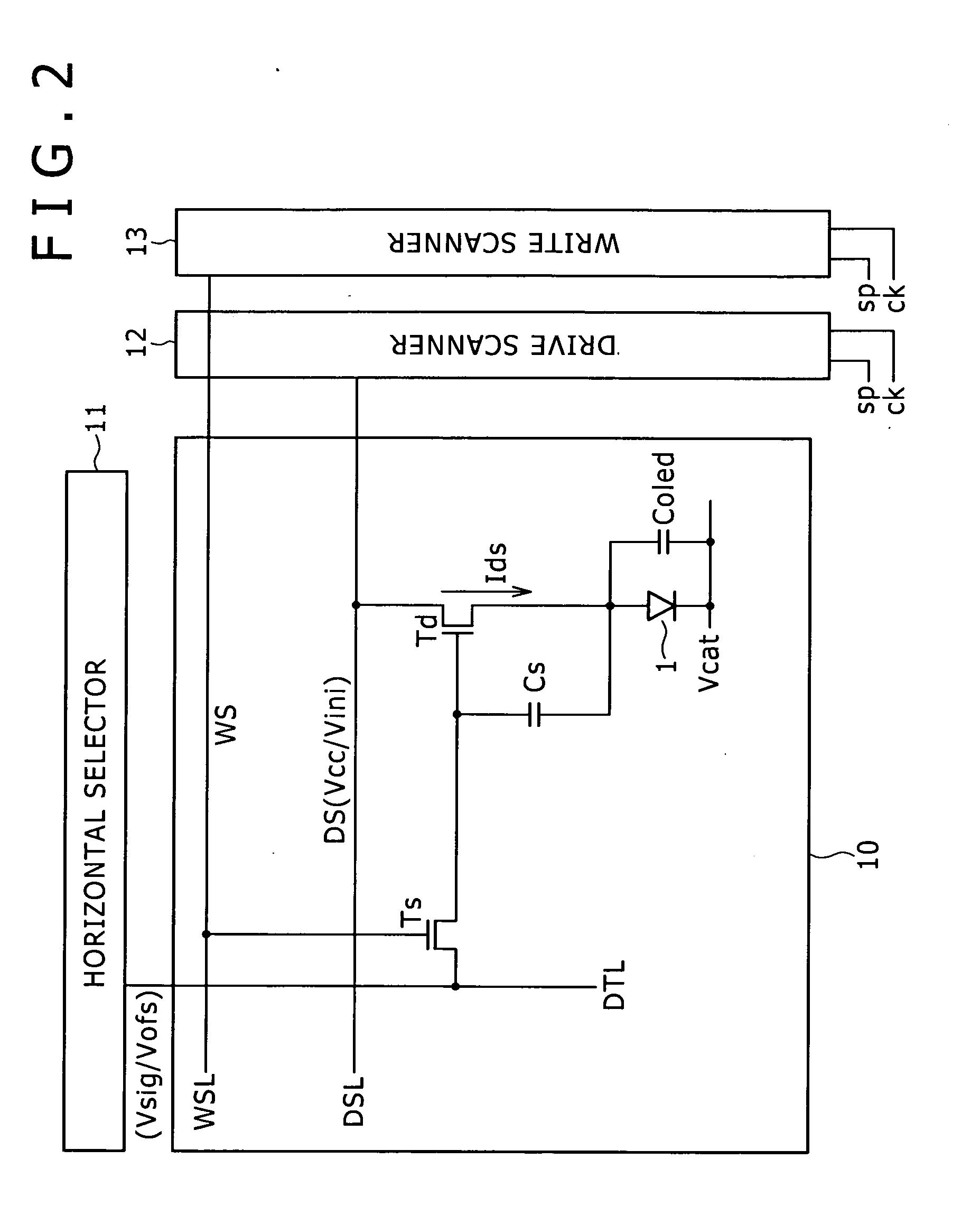
[0047]This organic EL display device employs organic EL elements as its light emitting elements and includes pixel circuits 10 that carry out light emission driving based on the active-matrix system.

[0048]As shown in the diagram, the organic EL display device has a pixel array 20 in which a large number of pixel circuits 10 are arranged in a matrix along the column direction and the row direction (on m rows×n columns). Each of the pixe...


PUM


Abstract

Disclosed herein is a display device including a pixel array configured to include pixel circuits arranged in a matrix having a light emitting element, driving transistor, sampling transistor, and hold capacitor. The display device further includes a signal selector, driving control scanner, and writing scanner. The signal selector alternately carries out supply of a video signal voltage in order from a beginning line to an end line in a unit and supply of a video signal voltage in order from an end line to a beginning line in a unit. The writing scanner outputs the pulse to the writing control lines in such a way that input of a video signal voltage in order from a beginning line to an end line in a unit and input of a video signal voltage in order from an end line to a beginning line in a unit are alternately carried out.

Description

BACKGROUND OF THE INVENTION[0001]1. Field of the Invention[0002]The present invention relates to a display device having a pixel array in which pixel circuits are arranged in a matrix and a display driving method thereof, and particularly to a display device employing e.g. an organic electro-luminescence element (organic EL element) as its light emitting element.[0003]2. Description of the Related Art[0004]For example, as disclosed in Japanese Patent Laid-Open No. 2003-255856 and Japanese Patent Laid-Open No. 2003-271095, image display devices employing an organic EL element for the pixels have been developed. The organic EL element is a self-luminous element and therefore has the following advantages over e.g. a liquid crystal display device: higher image visibility, no necessity for a backlight, higher response speed, etc. Furthermore, the luminance level (grayscale) of each light emitting element can be controlled based on the value of the current flowing through the light emitti...

Claims


Application Information

Patent Timeline
Patent Type & Authority Applications(United States)
IPC IPC(8): G09G5/10G09G3/30H05B44/00
CPCG09G3/3233G09G2310/0251G09G2300/0842
Inventor TOYOMURA, NAOBUMIUCHINO, KATSUHIDE
Owner JOLED INC
Why Eureka
Try Eureka