
Illuminated Vehicle Wheel With Bearing Seal Slip Ring Assembly

Inactive Publication Date: 2011-07-28
MICHELOTTI WILLIAM M
View PDF28 Cites 15 Cited by
  • Summary
  • Abstract
  • Description
  • Claims
  • Application Information

AI Technical Summary

Benefits of technology

[0011]It is another object of the present invention to provide a slip ring incorporated into a wheel bearing assembly operably connected to the vehicle power system, by which a vehicle wheel receives power through the bearing seal slip ring and external brush assembly, and which is operably connected to one or more arrays of light emitting diodes (LEDs) located on the vehicle wheel, particularly in recessed grooves provided in the edges of wheel struts to provide an attention-grabbing luminous glow to the wheel.
[0012]It is another object of the invention to improve upon prior art designs such that the bearing assembly including bearing seal slip ring and bearing may be easily replaced. It is another object of the invention so that the external brush assembly may be easily replaced.

Problems solved by technology

U.S. Pat. No. 6,116,763 (King) discloses a wheel illumination device requiring no external power and using magnetic and rotational forces to power the LEDs, however, such a system is inoperable when the wheels are not rotating.
The prior art devices use a number of different power systems, however, none of the prior art systems provide a generally-applicable design for a slip ring power transfer assembly to provide power to electrically operated lighting elements in a wheel that can be sold as a kit for installation in motorcycles made by many different manufacturers.

Method used


Image

  • Illuminated Vehicle Wheel With Bearing Seal Slip Ring Assembly
  • Illuminated Vehicle Wheel With Bearing Seal Slip Ring Assembly
  • Illuminated Vehicle Wheel With Bearing Seal Slip Ring Assembly

Examples


Embodiment Construction

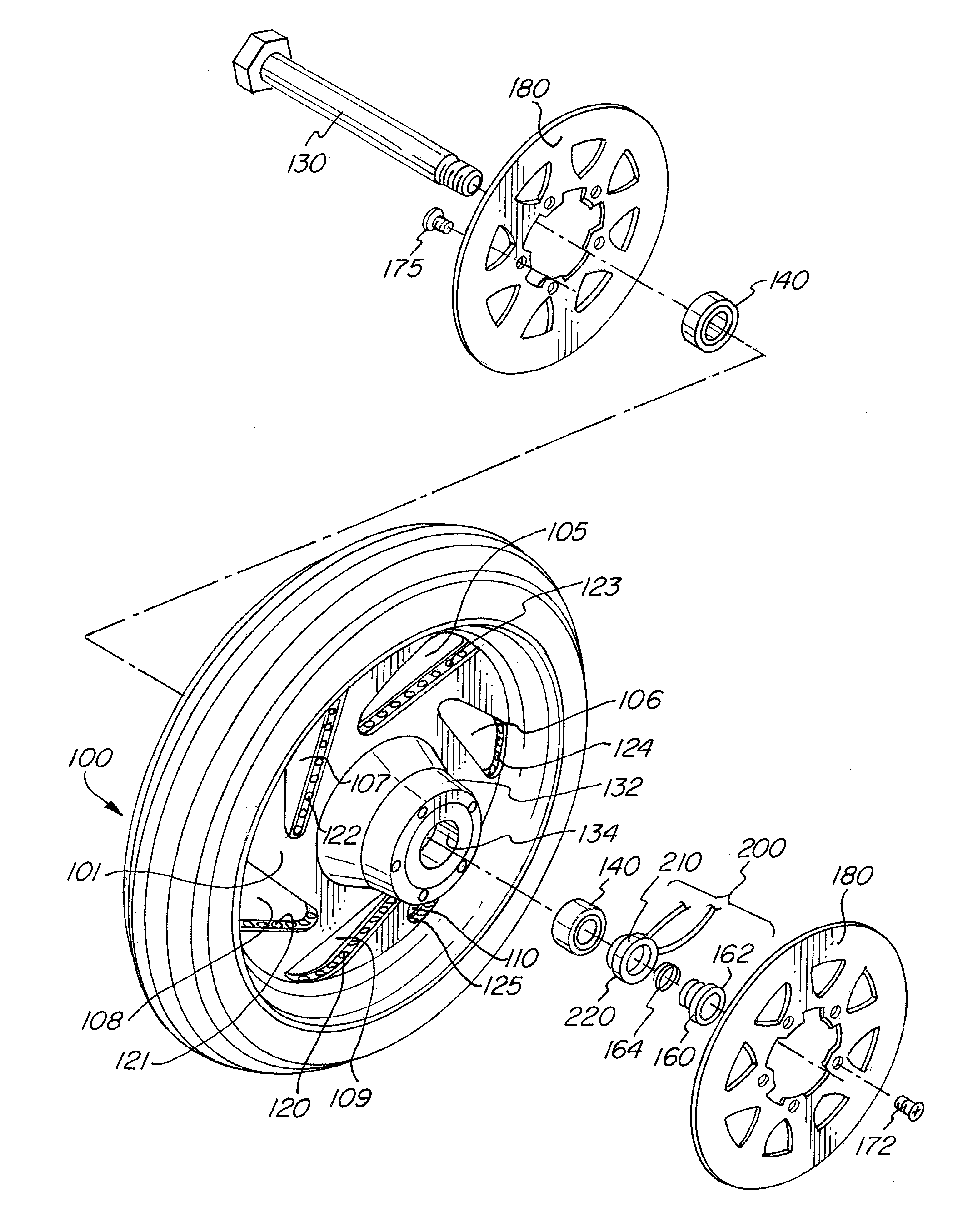
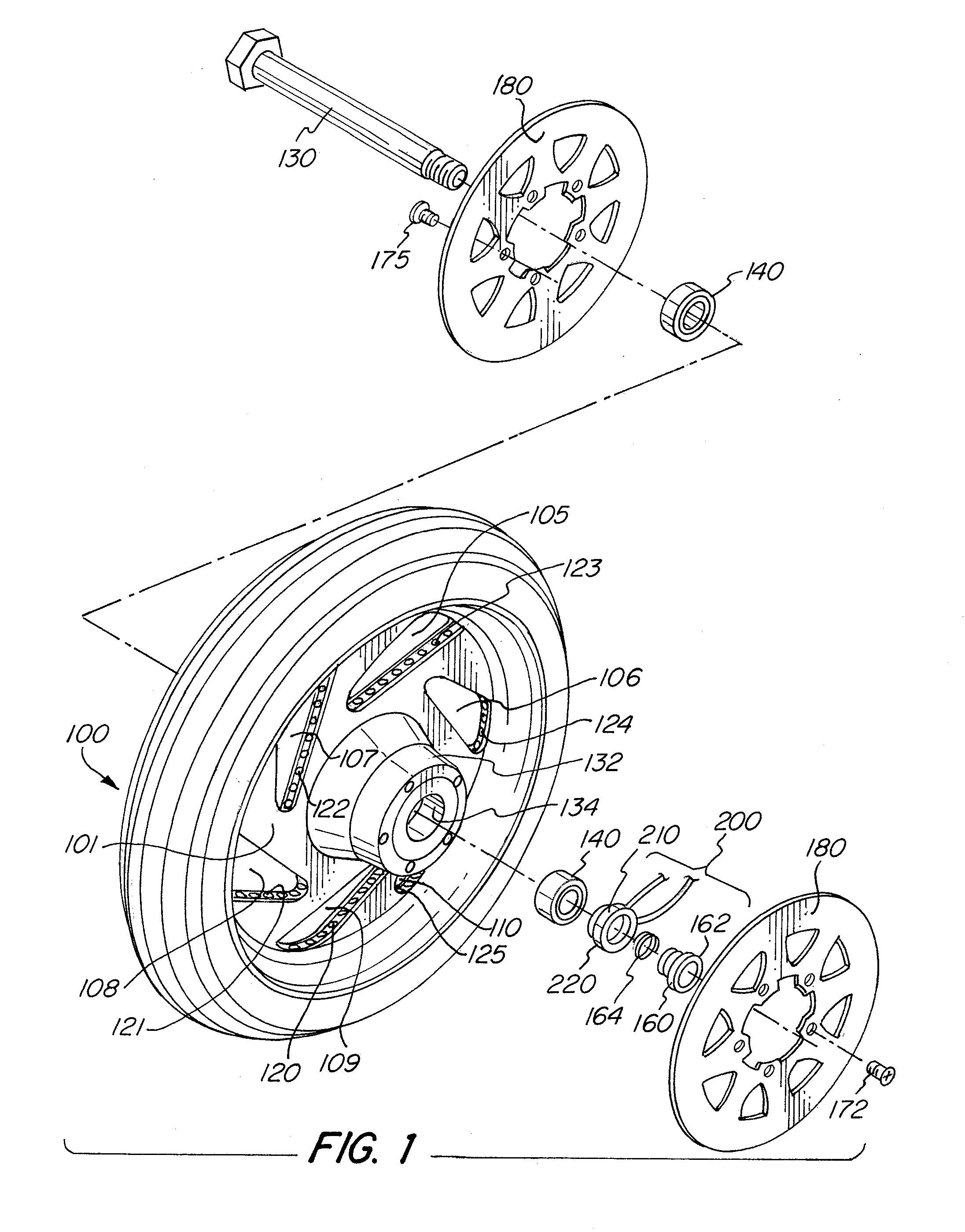
[0032]Referring to FIG. 1, a vehicle wheel 100 is shown having strut area 101 and cutaway areas 105, 106, 107, 108, 109 and 110. Arrays of electrically operated illumination elements such as strips of light emitting diodes (LEDs) 120, 121, 122, 123, 124 and 125 are provided in channels which extend around the inner perimeter of the struts (in other words, the LEDs surround the cutaway areas defined by the struts). When power is provided to the LEDs to energize them, the vehicle wheel is illuminated with an eye-catching glow. While FIG. 1 shows the strut area 101 and cutaway areas 105, 106, 107, 108, 109 and 110 of a particular design having triangular cutaway areas, the present invention also provides for cutaway areas be of a circular, oval, or rectangular shape, or other such shapes used for vehicle wheels

[0033]Wheel 100 has a hub 132 and is associated with an axle 130, and bearing 140. Brake discs 180 are affixed to wheel 100 by screws 172 / 175.

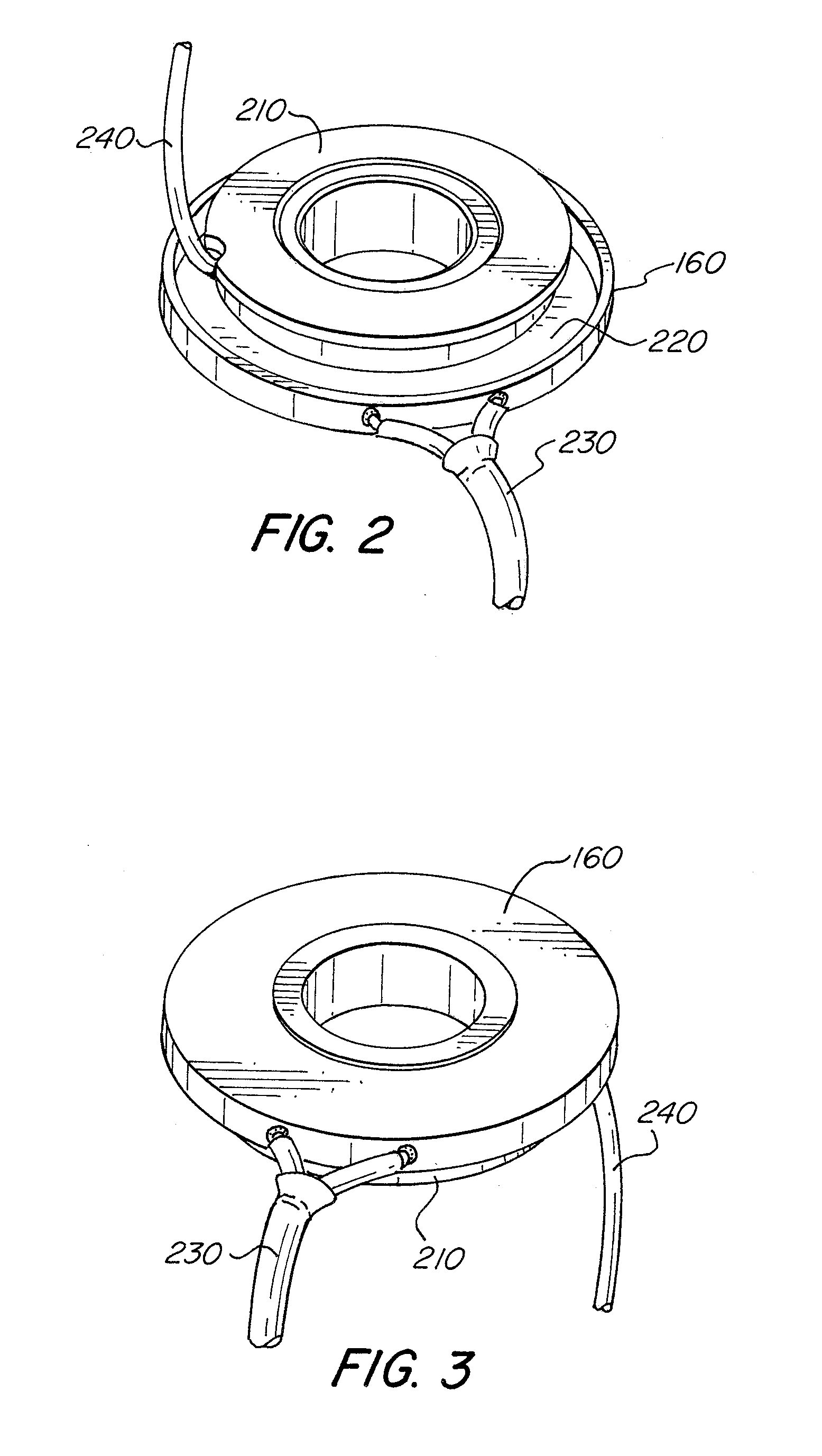
[0034]Slip ring assembly 200 is moun...


PUM

PropertyMeasurementUnit
Electrical conductivityaaaaaaaaaa
Electrical conductoraaaaaaaaaa
Resilienceaaaaaaaaaa

Abstract

An illuminated vehicle wheel assembly having arrays of illuminated electrical elements such as light emitting diodes, which are powered by the vehicle power systems by way of a slip ring assembly associated with the bearing or bearing seal of the vehicle wheel.

Description

[0001]The present application claims the benefit under 35 U.S.C. §119 (e) of Provisional Patent Application Ser. No. 61 / 299,199 for an Illuminated Wheel Bearing Seal Slip Ring Assembly filed on Jan. 28, 2010. The contents of Provisional Patent Application Ser. No. 61 / 299,199, filed on Jan. 28, 2010 are hereby incorporated by reference.FIELD OF INVENTION[0002]The present invention relates to the field of vehicular accessories, particularly, slip ring power transfer apparatus to transfer power to a rotating element such as a wheel, and most particularly, slip ring power transfer apparatus to provide power to electrically operated illumination elements such as LEDs located in a vehicle wheel.BACKGROUND OF THE INVENTION[0003]Motorcycle customization is a strong tradition among certain motorcycle riding communities. Custom motorcycle paint, exhaust, and fender systems are very popular. These customs have been further popularized by televisions shows such as “Orange County Choppers.”[0004...

Claims


Application Information

Patent Timeline
IPC IPC(8): B60B19/00B62J6/00H01R39/12B23P17/04
CPCB60B19/00B60B27/0047B60B2310/206B60B2360/10B60B2360/32Y10T29/49716B60Q1/326B60Y2200/12H01R39/10H01R39/12B60B2360/3412
Inventor MICHELOTTI, WILLIAM M.
Owner MICHELOTTI WILLIAM M
Learn More