Sequential image alignment

a technology of image alignment and square image, applied in the field of methods, can solve the problems of unwieldy design of optical sensors and relatively expensive capacitive silicon sensors

Inactive Publication Date: 2011-07-28
PRECISE BIOMETRICS AB
View PDF11 Cites 64 Cited by
  • Summary
  • Abstract
  • Description
  • Claims
  • Application Information

AI Technical Summary

Benefits of technology

[0012]In view of the above, an objective of the invention is to solve or at least reduce the problems discussed above. In particular, an objective is to provide an efficient way of using the plurality of images in sense of memory consumption.

Problems solved by technology

Optical sensors have the disadvantage of being unwieldy in design, on account or the lens system.
The capacitive silicon sensors are relatively expensive as they require a large silicon area.
A problem with swipe sensors is to efficiently use the plurality of images acquired by the sensor for checking of the fingerprint.

Method used


Image

  • Sequential image alignment
  • Sequential image alignment
  • Sequential image alignment

Examples


Embodiment Construction

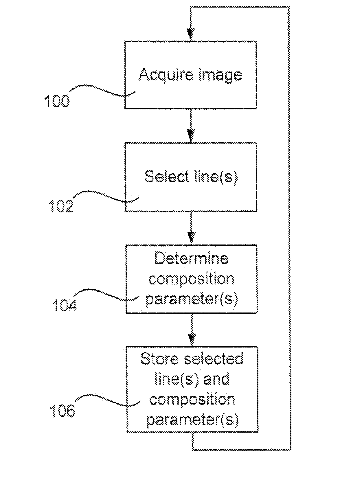
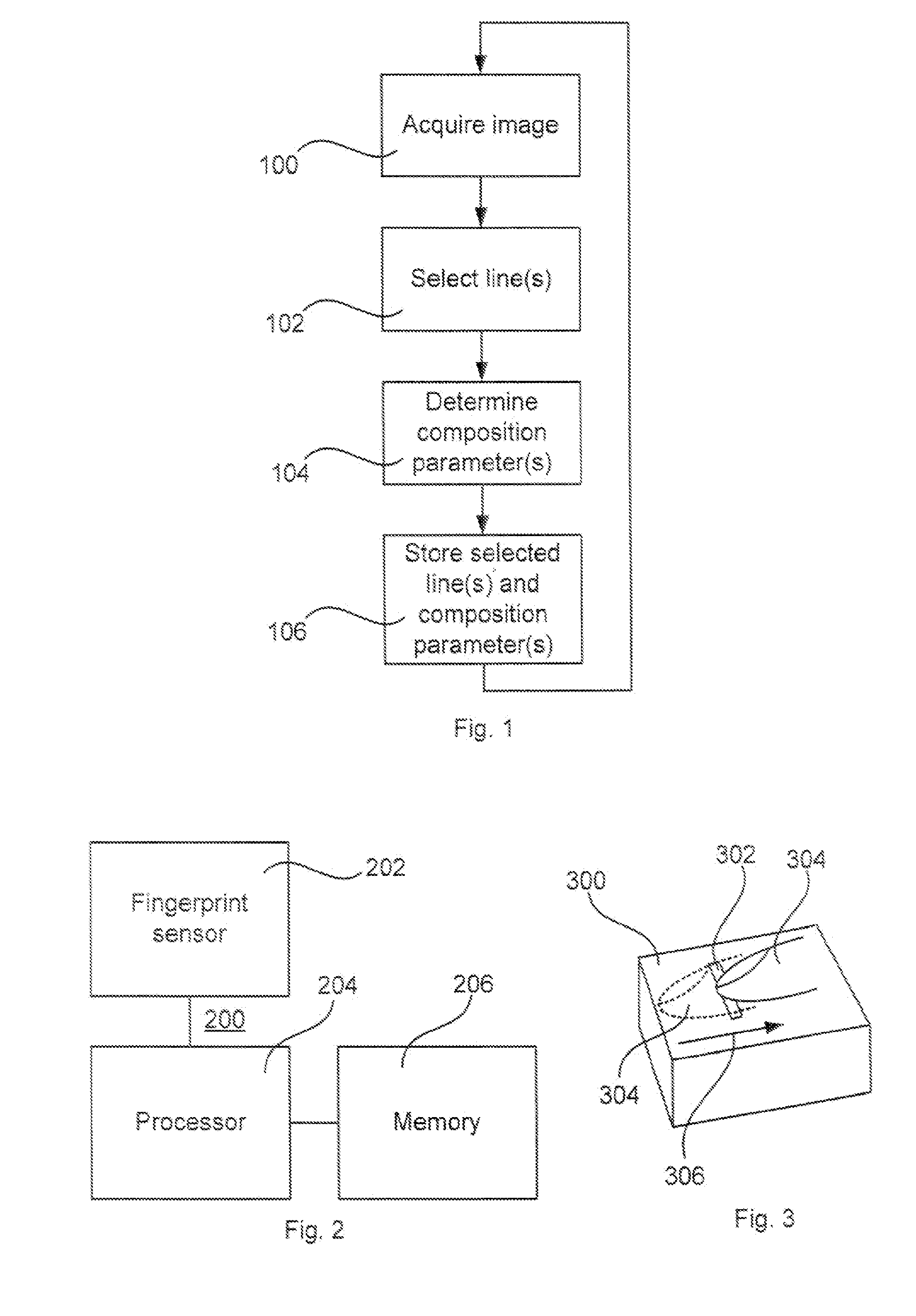
[0055]FIG. 1 is a flow chart illustrating a method according to an embodiment of the present invention. An image of a fingerprint is acquired in an image acquireing step 100. The image is acquired upon a relative movement between an image sensor and the finger to be imaged, e.g. by sweeping the finger over the sensor, while several images are acquired in sequence.

[0056]The sensor is preferably a swipe sensor, which has an elongated sensor area to which the relative movement of the finger is performed in a direction perpendicular to the elongation of the sensor. Normally, the width of the sensor is about the width of a normal fingertip, while the size of the sensor in the movement direction only is one or a few millimeters. Thereby, each acquired image comprises a part of the fingerprint.

[0057]Depending on the relative movement, the overlap between the sequentially acquired images may differ, and depending on direction and straightness of the relative movement, the alignment between ...


PUM


Abstract

A method for reading fingerprints is disclosed. The method comprises acquiring images of a fingerprint from a finger upon relative movement between the finger and an image sensor; selecting lines from said acquired images representing a new area of said fingerprint; determining composition parameters for each selected line: and storing said composition parameters and said selected lines such that a composite image comprising said selected lines is composabte. A corresponding fingerprint reading apparatus, a device, and a computer program are also disclosed.

Description

TECHNICAL FIELD[0001]The present invention relates to a method, a fingerprint reading apparatus, a device, and a computer program.BACKGROUND OF THE INVENTION[0002]It has been known from time immemorial that fingerprints can be used to identify people. Initially fingerprints were taken manually by inking the first joint of a finger and pressing this onto a sheet of paper. A pattern of lines was thus printed onto the sheet of paper, where the lines corresponded to the ridges and the spaces between the lines corresponded to the grooves in the skin of the finger. Now fingerprints are taken using sensors that detect the pattern on the skin on the part of the finger that is held against the sensor.[0003]Traditionally fingerprint technology has been used primarily for the identification of criminals, but in recent years it has also begun to be used for access control.[0004]Known access control systems are based on a person who is to be given access to something, recording his fingerprint u...

Claims


Application Information

Patent Timeline
Patent Type & Authority Applications(United States)
IPC IPC(8): G06K9/00
CPCG06K9/00026G06V40/1335
Inventor VALFRIDSSON, KRISTERNORDIN, BJORN
Owner PRECISE BIOMETRICS AB
Why Eureka
Try Eureka