Method For Manufacting Dental Implant Components

a technology for dental implants and components, applied in the field of dental implant systems, can solve the problems of reducing the precision of the final prosthesis, less than accurate impression of the condition of the patient's mouth,

Active Publication Date: 2011-07-28
BIOMET 3I LLC
View PDF99 Cites 60 Cited by
  • Summary
  • Abstract
  • Description
  • Claims
  • Application Information

AI Technical Summary

Problems solved by technology

Otherwise, a less than accurate impression of the condition of the patient's mouth is made.
Unfortun

Method used


Image

  • Method For Manufacting Dental Implant Components
  • Method For Manufacting Dental Implant Components
  • Method For Manufacting Dental Implant Components

Examples


Embodiment Construction

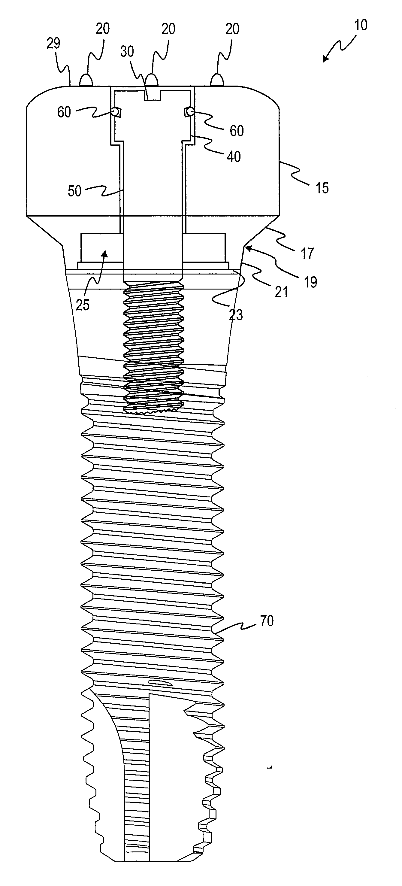
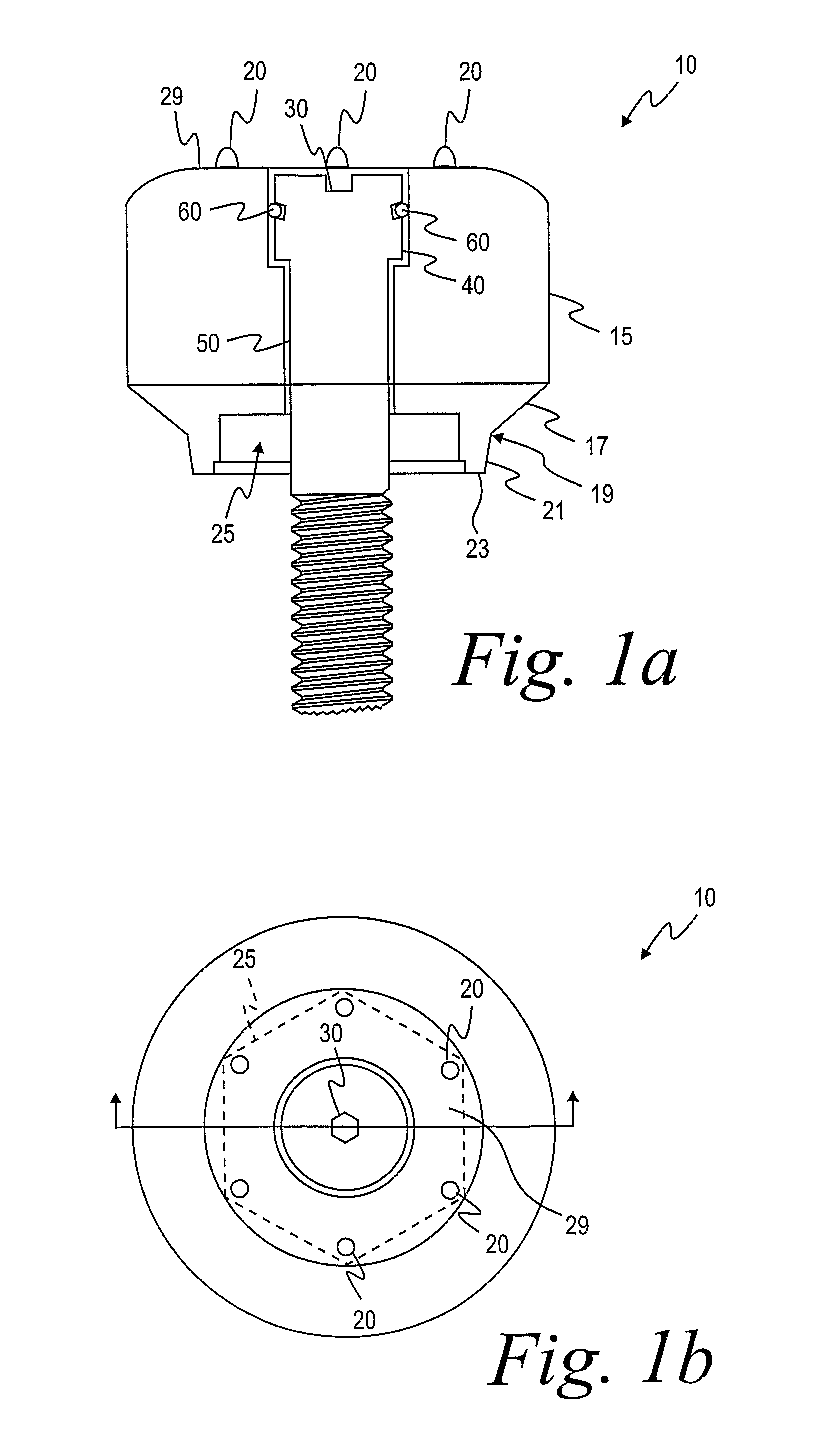
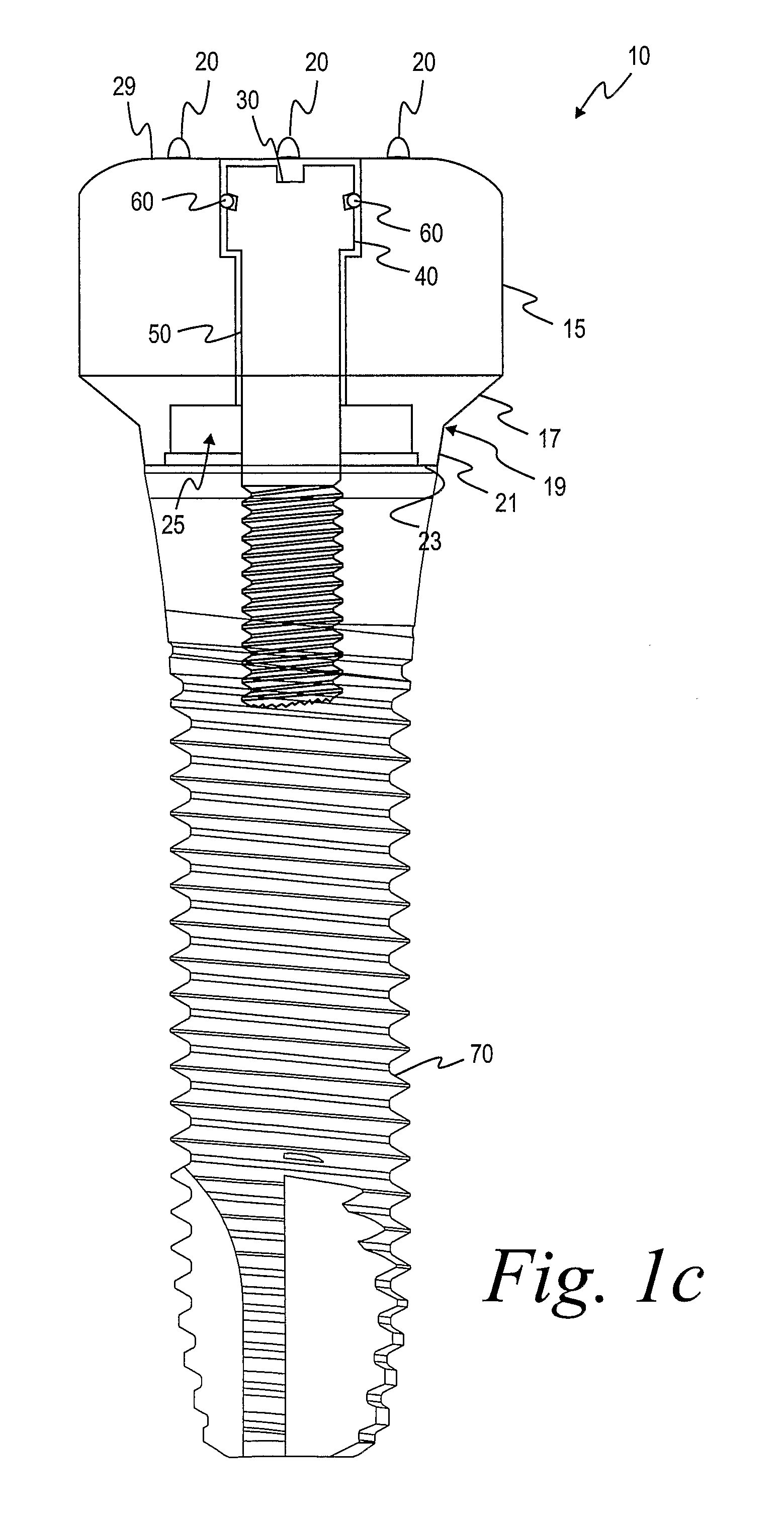
[0055]As shown in FIG. 1a and 1b, the healing abutment 10 of one embodiment of the present invention has a main body 15 with a generally circular cross-sectional shape, a first tapered section 17, a boundary 19, a second tapered section 21, an end surface 23, a hex socket 25 and dimensions that are generally suitable for replicating the emergence profile of a natural tooth. The first tapered section 17 extends downwardly from the main body 15 of the abutment 10 having a diameter at a boundary 19 that is generally larger than the implant (not shown). The boundary 19 separates the first tapered section 17 from the second tapered section 21 that terminates in the end surface 23. The second tapered section 21 is at an angle with the central axis of the implant that is generally in the range from about 5 degrees to about 15 degrees, with 10 degrees being preferable. Alternatively, the second tapered section 21 may be omitted such that the first tapered section 17 tapers directly to the d...


PUM


Abstract

A method for making a rapid prototype of a patient's mouth to be used in the design and fabrication of a dental prosthesis. The method takes an impression of a mouth including a first installation site having a dental implant installed in the first installation site and a gingival healing abutment having at least one informational marker attached to the dental implant. A stone model is prepared based on the impression, including teeth models and model markers indicative of the at least one informational marker. The model is scanned. Scan data is generated from the scanning. The scan data is transferred to a CAD program. A three-dimensional model of the installation site is created in the CAD program. The at least one informational marker is determined to gather information for manufacturing the rapid prototype. Rapid prototype dimensional information is developed. The rapid prototype dimensional information is transferred to a rapid prototyping machine which fabricate a rapid prototype of the patient's dentition as well as a dental implant analog position.

Description

FIELD OF INVENTION[0001]The present invention relates generally to dental implant systems. More particularly, the present invention relates to dental implant systems wherein an implant is implanted in an edentulous bone of the alveolar arches of the jaws.BACKGROUND OF THE INVENTION[0002]The dental restoration of a partially or wholly edentulous patient with artificial dentition is typically done in two stages. In the first stage, an incision is made through the gingiva to expose the underlying bone. An artificial tooth root, usually a dental implant, is placed in the jawbone for integration. The dental implant generally includes a threaded bore to receive a retaining screw holding mating components therein. During the first stage, the gum tissue overlying the implant is sutured and heals as the osseointegration process continues.[0003]Once the osseointegration process is complete, the second stage is initiated. Here, the gum tissue is re-opened to expose the end of the dental implan...

Claims


Application Information

Patent Timeline
IPC IPC(8): A61C8/00G06F19/00A61C5/77
CPCA61C8/00A61C8/0001A61C13/0004A61C13/0013G06F17/50A61C9/0053A61C9/008A61C13/34B29C67/0088A61C13/0018B33Y80/00B33Y50/00B29C64/386G16H20/40G06F30/00B33Y50/02G05B15/02
Inventor POWELL, THEODORE M.AMBER, JOHN T.BERCKMANS, III, BRUCESUTTIN, ZACHARY B.
Owner BIOMET 3I LLC
Why Eureka
Try Eureka