Rapid prototyped transfer tray for orthodontic appliances

a technology for orthodontic appliances and transfer trays, applied in the field of transfer trays, can solve the problems of requiring the intervention of an operator in the conventional process of thermoforming or casting the transfer tray, incurring additional time or materials costs, and laborious and time-consuming preparation of the transfer trays for the treating professional or lab technician, so as to facilitate the engagement and disengagement of the transfer tray from the appliance, and reduce the travel distance of the transfer tray. , the effect of reducing the smea

Inactive Publication Date: 2011-04-21
3M INNOVATIVE PROPERTIES CO
View PDF44 Cites 124 Cited by
  • Summary
  • Abstract
  • Description
  • Claims
  • Application Information

AI Technical Summary

Benefits of technology

[0015]By configuring the gingival edge of the transfer tray to intersect each receptacle, the treating professional gains particular advantages during the bonding procedure. First, the transfer tray only partially encapsulates each appliance, thereby facilitating both engagement and disengagement of the transfer tray from appliances. Second, positioning the receptacles at the gingival edge of the transfer tray also reduces the travel distance of the tray during seating, thereby minimizing adhesive smearing during the bonding (particularly when using two-part chemical cure adhesives). This transfer tray may be pre-loaded with orthodontic appliances by the manufacturer or alternatively may be loaded by the treating professional prior to bonding. By automating the tray manufacturing based directly on digital data, this method also offers improved product consistency, compared with manually prepared transfer trays.
[0016]The transfer tray may also include a thin frangible web of material that partially extends across gingival portions of the appliance, such that the appliance is securely retained in the tray prior to bonding. Once the appliance has been bonded to the patient's dental structure, the frangible web can then be fractured and the tray removed from the patient's mouth by urging the transfer tray in the occlusal direction. The presence of a frangible web is particularly advantageous since it provides both convenient loading and retention of the appliance into the tray, as well as easy detachment of the tray from the patient's dental structure. Detachment of the tray in the occlusal direction is convenient and comfortable for the patient since it does not involve pulling the tray outward against the cheeks or lips. Occlusal tray removal is also helps minimize the risk of accidentally debonding the newly bonded appliances, since it avoids the need to pull the appliances away from the tooth surface in the labial direction (or lingual direction in the case of lingual appliances).
[0017]The use of rapid prototyping techniques to fabricate the transfer tray is advantageous because it provides the freedom for the receptacle geometry to be adapted for easy engagement and disengagement of the orthodontic appliance from the tray. Other known fabrication methods, such as casting and thermoforming, fully surround t

Problems solved by technology

The preparation of transfer trays can be, unfortunately, both laborious and time-consuming for the treating professional or lab technician.
The conventional process of either thermoforming or casting the tray requires the intervention of an operator and is subject to human error, particularl

Method used


Image

  • Rapid prototyped transfer tray for orthodontic appliances
  • Rapid prototyped transfer tray for orthodontic appliances
  • Rapid prototyped transfer tray for orthodontic appliances

Examples


example

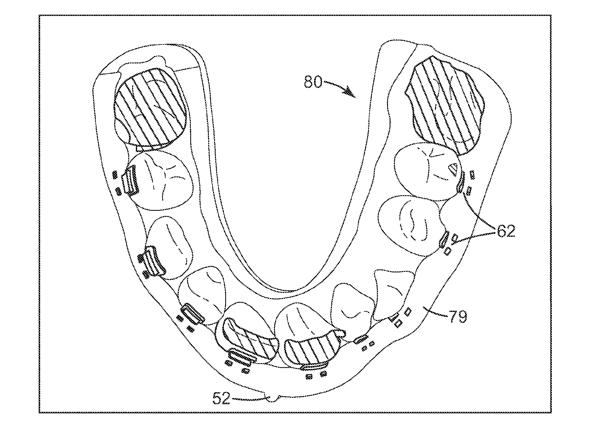
[0082]An exemplary transfer tray was prepared using a scanned 3D virtual model of a patient as well as the 3D solid models of an upper 5×5 set of VICTORY SERIES brand orthodontic brackets (3M Unitek, Monrovia, Calif.) provided in STL format. A virtual model of the patient's arch was obtained using a digital scan of an orthodontic stone impression of a patient's upper dental arch. THREE-MATIC software (Materialise Group in Leuven, Belgium) was then used to construct a virtual model of the transfer tray. The 5×5 set of upper orthodontic brackets was virtually bonded to the model. A three-section integral stop member was derived to matingly engage the occlusal contours of the left first molar, right first molar and the left and right central teeth. A single guidance line was manually traced along the facial surfaces of the virtual brackets by an operator, and this guidance line was subsequently used to derive a smoothed outer surface that was offset by 3.5 millimeters in the labial dir...


PUM

PropertyMeasurementUnit
Structureaaaaaaaaaa
Sizeaaaaaaaaaa
Flexibilityaaaaaaaaaa

Abstract

The present invention is directed to computer-implemented methods of making a transfer tray using rapid prototyping techniques, where the gingival edge of the tray is defined to intersect with at least one receptacle for receiving an orthodontic appliance. This tray configuration helps to minimize the travel distance of the tray when placing the tray over a patient's teeth, while also preserving a high degree of mechanical retention for retaining the appliance until such time that the appliance is bonded to the tooth. Other aspects of the tray and associated methods of bonding are directed to a frangible web that extends over the gingival portion of the receptacle and fractures to facilitate tray removal after bonding.

Description

BACKGROUND OF THE INVENTION[0001]1. Field of the Invention[0002]This invention relates to transfer trays that are used by orthodontic treating professionals to bond appliances to the teeth of an orthodontic patient. The invention is also related to methods for making such transfer trays.[0003]2. Description of the Related Art[0004]Orthodontics is the area and specialty of dentistry associated with the supervision, guidance and correction of malpositioned teeth to desired locations in the oral cavity. Orthodontic treatment can improve the patient's facial appearance, especially in instances where the teeth are noticeably crooked or where the upper and lower teeth are out of alignment with each other. Orthodontic treatment can also enhance the function of the teeth by providing better occlusion during mastication.[0005]One common type of orthodontic treatment involves the use of tiny, slotted appliances known as brackets. The brackets are fixed to the patient's teeth and a resilient, ...

Claims


Application Information

Patent Timeline
IPC IPC(8): A61C7/16G06F19/00
CPCA61C7/146A61C7/002B29C64/00B29C64/386B33Y50/00B33Y10/00B33Y80/00B29C64/393B29C64/188B33Y50/02G05B19/4099G05B2219/35134G05B2219/49007
Inventor KIM, SUNGRABY, RICHARD E.
Owner 3M INNOVATIVE PROPERTIES CO
Why Eureka
Try Eureka