Slat wall systems

a technology of sliding wall and sliding plate, which is applied in the direction of washstands, scaffold accessories, lightening support devices, etc., can solve the problems of reducing stability, limiting the options of users, and not pleasing to the eye, so as to achieve the effect of convenient manufacture and installation

Inactive Publication Date: 2011-08-04
DOMESTIC INVESTMENT GRP
View PDF25 Cites 8 Cited by
  • Summary
  • Abstract
  • Description
  • Claims
  • Application Information

AI Technical Summary

Benefits of technology

[0006]Another object and feature of the present invention is to provide a slat wall system that conceals fasteners used for installation. Another object and feature of the present invention is to provide a slat wall system that provides double-slot support for peg supports. Another object and feature of the present invention is to provide a slat wall system that is easy to install. Another object and feature of the present invention is to provide a slat wall system that creates symmetry allowing double-slot peg supports to be installed across panel boundaries. Another object and feature of the present invention is to provide a slat wall system that is easy to manufacture. Another object and feature of the present invention is to provide a slat wall system that presents a pleasing and finished appearance
[0007]It is an additional primary object and feature of the present invention to provide slat wall system that is safe, inexpensive, easy to clean, and handy. Other objects and features of this invention will become apparent with reference to the following descriptions.SUMMARY OF THE INVENTION
[0008]In accordance with a preferred embodiment hereof, the present invention provides a slat wall system that conceals fasteners in the finished installation, provides double-slot peg supports within and across panels, and is easy to manufacture and install.

Problems solved by technology

Slat walls of various designs are on the market, but are not aesthetically pleasing to some, as the fasteners for fastening the slat wall panels are visible after installation.
In addition, some designs create asymmetries that prevent attachment of pegs across panel boundaries, thereby limiting the options of the user.
Some slat wall designs engage peg supports in a single slot on the slat wall, thereby reducing stability.

Method used


Image

  • Slat wall systems
  • Slat wall systems
  • Slat wall systems

Examples


Embodiment Construction

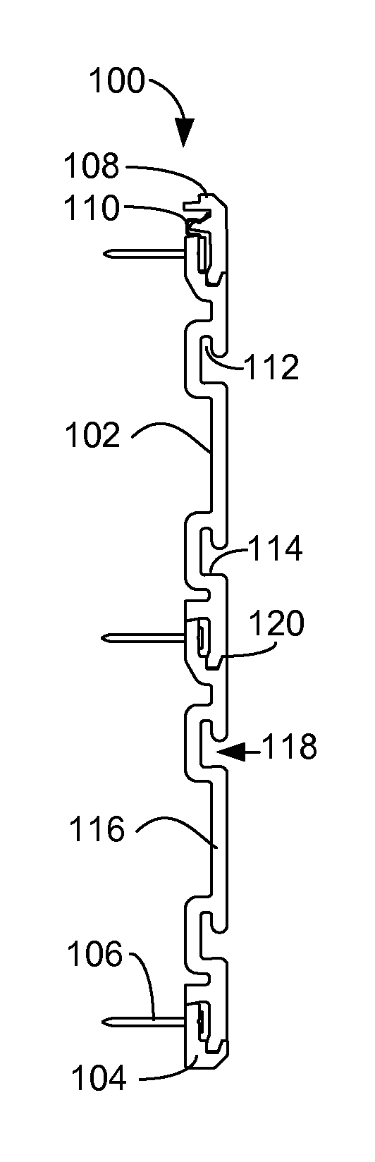
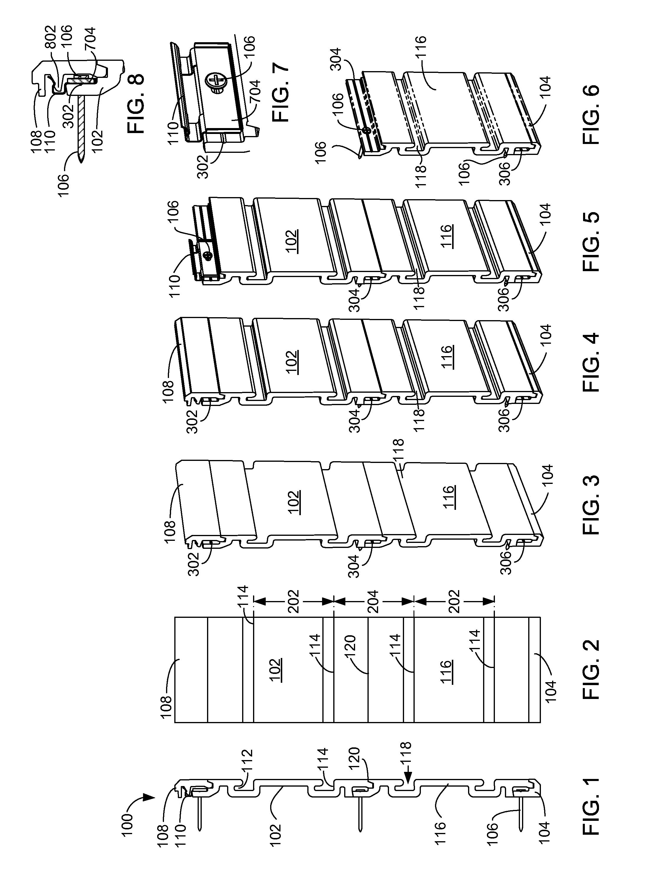
[0040]FIG. 1 is a side elevation view illustrating an exemplary slat wall system 100, according to a preferred embodiment of the present invention. The present invention provides a slat wall system 100 with first and second primary panels 116 and 102, a bottom panel 104, and a top panel 108. Top panel 108 is attached with the aid of a clip 110 (see FIGS. 7 and 8 for detail). The panels 104, 116, 102, and 108 are attached to a wall using fasteners 106 (one of three labeled). The panels 104, 116, 102, and 108 are made of a substantially rigid material. Each primary panel 102 and 116 has two slots 118 (one of four labeled), and each slot 118 has a floor 114 (one of four labeled) and a flange channel 112 (one of four labeled). A seam 120 is formed by joining panels 116 and 102. Various numbers of primary panels 102 and 116 may be connected together to create a slat wall system 100 of any desired height.

[0041]FIG. 2 is a front elevation view illustrating an exemplary slat wall system, ac...


PUM


Abstract

A combination of interlocking primary, top, and bottom interlocking panels (or slats) and slat wall pegs, where the primary panels each have two horizontal spaced-apart slots positioned such that the spacing between slots on a panel and slots across a panel boundary is the same. The interlocking features conceal fasteners that are used proximate the interlock, providing an improved appearance. The top panels attach by spring clips for manual installation and removal. The bottom panels fasten to the wall. Attachment flanges on primary and bottom panels have a groove for fastener alignment. The pegs have resilient arcuate bases with a top flange for engaging a flange channel in the top of a slot and a bottom flange for engaging a floor and back wall of a lower slot. Pegs may be slotted for ease of storage.

Description

RELATED APPLICATIONS[0001]This application claims the benefit of U.S. Provisional Patent Application Ser. No. 61 / 300,008 filed Jan. 31, 2010 to the same inventor.FIELD OF THE INVENTION[0002]This invention relates to a slat wall system for storing tools and other objects on a wall having movable protrusions of various sorts. The invention further relates to a slat wall system in which the means for fastening the slat wall panels to a wall are concealed in the installed product.BACKGROUND[0003]Slat walls of various designs are on the market, but are not aesthetically pleasing to some, as the fasteners for fastening the slat wall panels are visible after installation. In addition, some designs create asymmetries that prevent attachment of pegs across panel boundaries, thereby limiting the options of the user. Some slat wall designs engage peg supports in a single slot on the slat wall, thereby reducing stability.[0004]Therefore, a need exists for a slat wall system that conceals fasten...

Claims


Application Information

Patent Timeline
Patent Type & Authority Applications(United States)
IPC IPC(8): E04B2/46E04C2/38A47B96/00
CPCA47B96/00E04C2/38E04B2/46E04F13/0894E04F13/12A47F5/0846
Inventor CARTER, GARY KEITH
Owner DOMESTIC INVESTMENT GRP
Why Eureka
Try Eureka