Fill-up control valve device

a control valve and valve body technology, applied in the direction of valve operating means/releasing devices, mechanical equipment, transportation and packaging, etc., can solve the problems of increasing the pressure in the casing and the fuel tank, and the possibility of additional fuel feed, etc., to achieve stable time duration, easy structure, and easy stabilization

Inactive Publication Date: 2011-08-04
KYOSAN DENKI KABUSHIKI KAISHA
View PDF15 Cites 20 Cited by
  • Summary
  • Abstract
  • Description
  • Claims
  • Application Information

AI Technical Summary

Benefits of technology

[0032]According to a still further feature of the invention, for example, as defined in the claim 4, the fuel pooling portion is integrally formed with the vessel portion at a lower side thereof. According to such feature, it is possible to easily make the structure, according to which the liquid fuel in the vessel portion flows into the fuel pooling portion.
[0033]According to a still further feature of the invention, for example, as defined in the claim 5, a cross sectional area of the fuel drain through-hole is gradually reduced from an inner side toward an outer side of the vessel portion. According to the above feature, the cross sectional area of the fuel drain through-hole is minimum at its downstream end and is gradually enlarged toward its upstream end. As a result, the flow characteristic of the liquid fuel, which enters the fuel drain through-hole at the upstream end (at which the cross sectional area is maximum), flows through the fuel drain through-hole and flows out from the downstream end thereof, can be easily stabilized. In addition, it is possible to stabilize the time duration for keeping the valve closed condition by the float valve unit.
[0034]The structure of the fuel drain through-hole, the cross sectional area of which is gradually reduced from the upper side toward the lower side, can be easily realized by making an inner peripheral surface of the fuel drain through-hole as a tapered surface, as defined in the claim 6.
[0035]According to a still further feature of the invention, for example, as defined in the claim 7, a fuel guiding portion is formed at the fuel drain through-hole so that the liquid fuel flows along the fuel guiding portion. According to such feature, it is possible to easily stabilize the flow characteristic of the liquid fuel flowing through the fuel drain through-hole, by making the liquid fuel to flow along the fuel guiding portion. In addition, it is possible to stabilize the time duration for keeping the valve closed condition by the float valve unit.
[0036]The fuel guiding portion can be easily formed, as defined in the claim 8, when the fuel guiding portion is composed of an annular projecting portion downwardly projecting from an outer periphery of a lower end of the fuel drain through-hole, and a lower end surface of the annular projecting portion is inclined with respect to an axial line of the fuel drain through-hole.
[0037]According to a still further feature of the invention, for example, as defined in the claim 9, the vessel portion has a side wall portion, which functions as a float guiding portion, so that the float valve unit is guided by the float guiding portion when it is moved in a vertical direction. Since it is not necessary to provide the float guiding portion separately from the vessel portion, a structure of the casing can be simplified.

Problems solved by technology

However, since the second ventilation hole is formed at the casing at such a position higher than the second predetermined level which is raised in the casing, the pressure in the casing and the pressure in the fuel tank are gradually counterbalanced.
It is, therefore, a problem that additional fuel feed may become possible even in the case that the fuel tank is filled up with the fuel.

Method used


Image

  • Fill-up control valve device
  • Fill-up control valve device
  • Fill-up control valve device

Examples


first embodiment

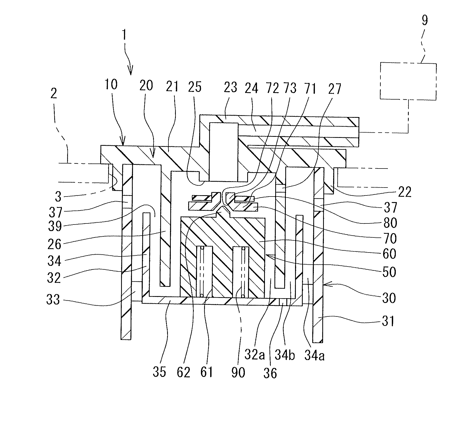
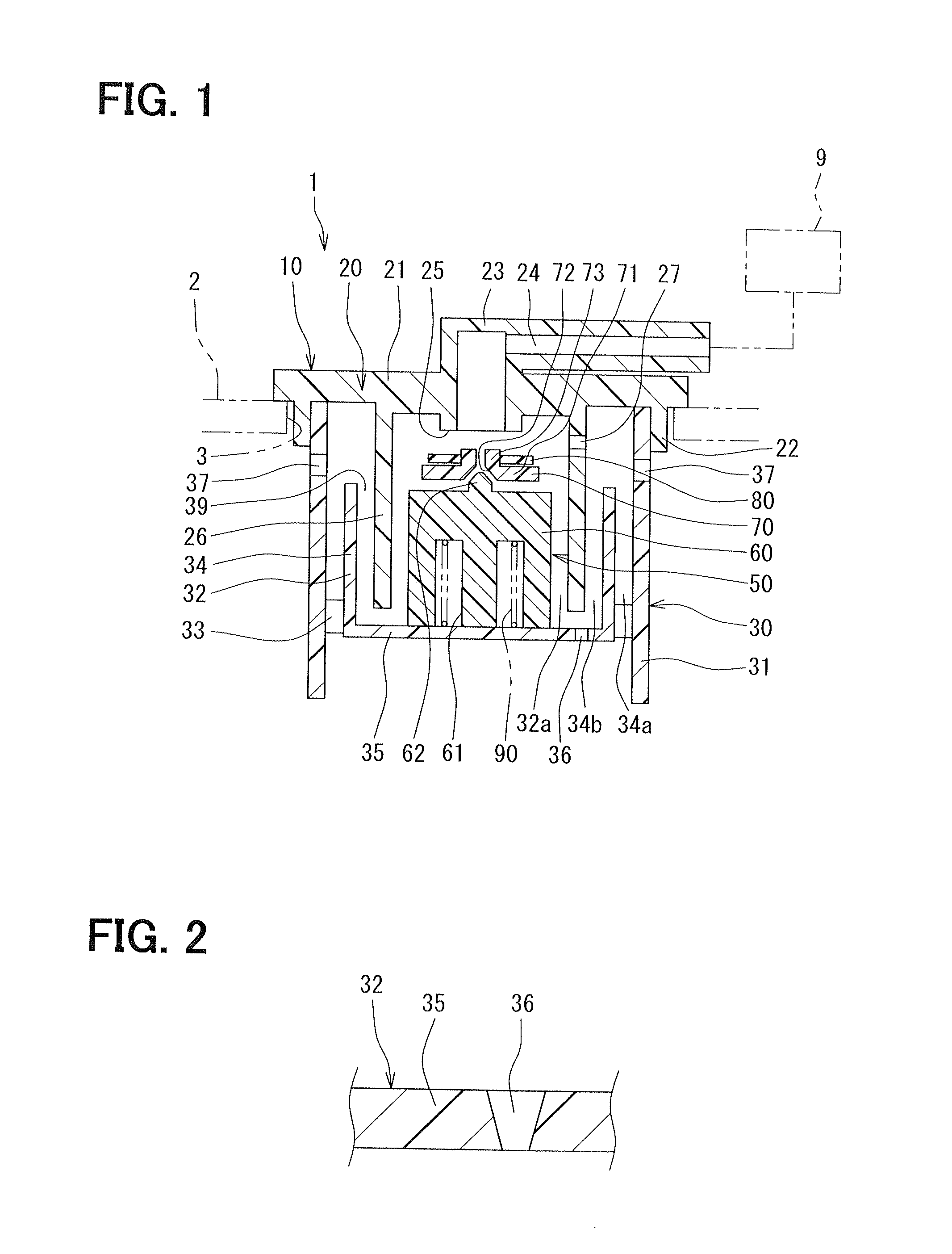
[0050]FIG. 1 is a schematic cross-sectional view showing an outlined structure of a fill-up control valve device 1 according to a first embodiment, to which the present invention is applied. And FIG. 2 is a schematic cross sectional view showing a relevant portion of a vessel portion 32 of the fill-up control valve device 1.

[0051]As shown in FIG. 1, the fill-up control valve device 1 is attached to an opening 3 formed at an upper side wall of a fuel tank 2, which is for example mounted to a vehicle. The fill-up control valve device 1 is a valve device for opening and / or closing a ventilation passage 24, which connects an inside space of the fuel tank with a canister 9 located at an outside of the fuel tank 2, so that the fuel tank 2 is operatively communicated to the canister 9 depending on a liquid surface level (a liquid surface position) of liquid fuel in the fuel tank 2.

[0052]As shown in FIG. 1, the fill-up control valve device 1 is composed of a casing 10 and a float valve unit...

second embodiment

[0086]A second embodiment of the present invention will be explained with reference to FIG. 4.

[0087]The second embodiment differs from the first embodiment in a structure of the fuel drain through-hole formed at the closed end bottom of the vessel portion 32. The same reference numerals to the first embodiment are used in the second embodiment for designating the same or similar parts to the first embodiment.

[0088]As shown in FIG. 4, according to the present embodiment, a fuel drain through-hole 136, having a small diameter, is formed at the closed end bottom 35 of the vessel portion 32, so that the through-hole 136 passes through the closed end bottom 35 in the vertical direction. An inner peripheral surface of the fuel drain through-hole 136 is a cylindrical surface, so that a cross sectional area of the through-hole 136 has the same value from its upper end to a lower end. As in the same manner to the first embodiment, the cross sectional area of the through-hole 136 is made to b...

third embodiment

[0091]A third embodiment of the present invention will be explained with reference to FIGS. 5 to 9.

[0092]The third embodiment differs from the first embodiment in that a fuel pooling tank, into which the liquid fuel flows from the vessel portion 32, is provided. The same reference numerals to the first embodiment are used in the third embodiment for designating the same or similar parts to the first embodiment.

[0093]As shown in FIG. 5, the fill-up control valve device 1 is fixed to the ceiling portion of the fuel tank 2 of the vehicle, and a fuel pooling portion 230 (corresponding to the fuel pooling tank) is formed at a lower side of the vessel portion 32 of the casing 10.

[0094]An annular extending portion 234 is provided at the lower casing part 30 of the casing 10 in such a manner that the annular extending portion 234 extends in the downward direction from an outer periphery of the closed end bottom 35 of the vessel portion 32. The annular extending portion 234 is integrally for...


PUM


Abstract

A casing has a vessel portion, in which a float valve unit is arranged. A fuel drain through-hole having a small diameter is formed at a closed end bottom of the vessel portion. A cross sectional area of the fuel drain through-hole is extremely smaller than an opening area of an inlet port, so that fuel discharging speed of the liquid fuel from the vessel portion through the fuel drain through-hole is suppressed to a small value. As a result, a fuel holding time of the liquid fuel in the vessel portion, which has entered into the vessel portion from the inlet port, is made longer.

Description

CROSS REFERENCE TO RELATED APPLICATION[0001]This application is based on Japanese Patent Applications No. 2010-021592 filed on Feb. 2, 2010 and No. 2010-185465 filed on Aug. 20, 2010, the disclosures of which are incorporated herein by reference.FIELD OF THE INVENTION[0002]The present invention relates to a fill-up control valve device provided in a ventilation passage communicating an inside space of a fuel tank with an outside space.BACKGROUND OF THE INVENTION[0003]A fill-up control valve device is known in the art, for example, as disclosed in Japanese Patent Publication No. 2004-257264 (corresponding to U.S. Pat. No. 6,994,103 B2). The fill-up control valve device has a float valve unit which is arranged in a casing attached to a fuel tank, wherein the floating valve unit floats on liquid fuel. When a fuel liquid level in the fuel tank is raised and reaches at a first predetermined level (which corresponds to a fuel filled-up level), the liquid fuel enters the casing through a v...

Claims


Application Information

Patent Timeline
Patent Type & Authority Applications(United States)
IPC IPC(8): F16K31/18
CPCF16K31/18Y10T137/0874Y10T137/7358Y10T137/3099B60K15/03519B60K2015/03289F16K24/044B60K15/035B60K2015/03576B60K15/03504B60K2015/03509
Inventor TAGAMI, HIROYASUZUKI, KEIJI
Owner KYOSAN DENKI KABUSHIKI KAISHA
Why Eureka
Try Eureka