
Liquid mixing apparatus

a technology of liquid mixing apparatus and mixing chamber, which is applied in the direction of positive displacement liquid engine, separation process, instruments, etc., can solve the problems of difficult to achieve reduced size and integration, and the mixing of turbulent flow cannot be expected, so as to reduce the size and efficiency of mixing liquids in a short time

Inactive Publication Date: 2011-08-04
CANON KK
View PDF4 Cites 4 Cited by
  • Summary
  • Abstract
  • Description
  • Claims
  • Application Information

AI Technical Summary

Benefits of technology

The present invention is a liquid mixing apparatus that can efficiently mix liquids quickly. It is small and easy to integrate. The apparatus includes a flow channel, a vortex-flow generating unit, a directional-flow generating unit, and a switching unit that can switch between the two. This allows for the efficient mixing of liquids without the need for an oblique electric field. The technical effects of this invention are improved liquid mixing in a compact design and easy integration.

Problems solved by technology

In a very small flow channel, mixing by turbulent flow cannot be expected because the Reynolds number is low.
As a result, it may be difficult to achieve reduced size and integration.

Method used


Image

  • Liquid mixing apparatus
  • Liquid mixing apparatus
  • Liquid mixing apparatus

Examples


first embodiment

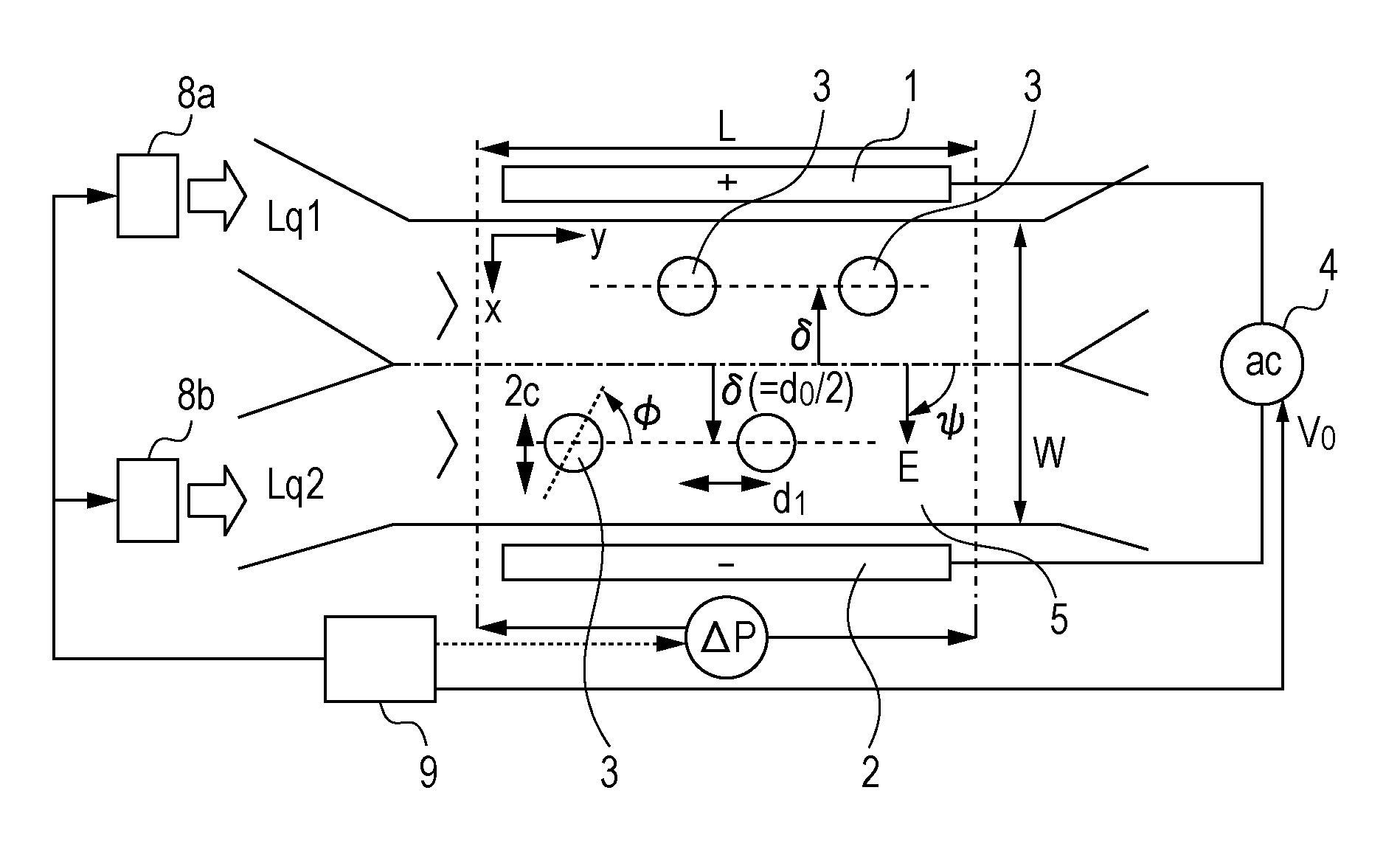
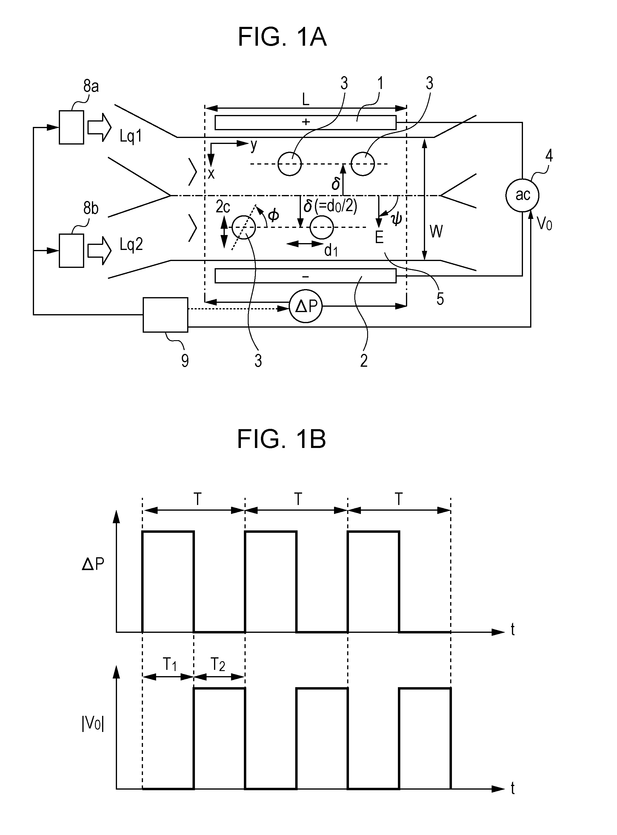
[0048]FIG. 1A is a sectional view of a mixing device according to a first embodiment. In the figure, reference numerals 1 and 2 denote a pair of electrodes, reference numerals 3 denote conductive members, reference numeral 4 denotes a power supply, and reference numeral 5 denotes a flow channel having a width w (=100 μm), a length L (=225 μm), and a depth D2 (>w). The flow channel 5 is filled with water or a solution that can be polarized, such as an electrolytic aqueous solution. Here, the pair of electrodes 1 and 2 are provided for applying a DC electric field or an AC electric field to the flow channel. The electrodes 1 and 2, the power supply 4, and the conductive members 3 constitute a vortex-flow generating unit that generates a vortex flow in a liquid in the flow channel.

[0049]Reference numerals 8a and 8b denote pumps serving as directional-flow generating units that are connected to end faces of the flow channel 5 and that generate flow in a direction along the flow channel....

second embodiment

[0074]FIG. 13 illustrates the feature of a liquid mixing apparatus according to a second embodiment of the present invention. The mixing apparatus according to the second embodiment includes directional-flow generating units 61a and 61b instead of the directional-flow generating units 8a and 8b (pumps) in the first embodiment.

[0075]The directional-flow generating units 61a and 61b are formed by disposing suppressing members 65a on respective sides of an elliptical conductive member 13a and by disposing suppressing members 65b on respective sides of an elliptical conductive member 13b. The suppressing members 65a and 65b suppress a flow in a reverse direction in a liquid flow that is generated by applying an electric field to conductive members.

[0076]Reference numeral 62 denotes a vortex-flow generating unit that is of the same type as that in the first embodiment.

[0077]In the mixing apparatus according to the second embodiment, a power supply connected to the vortex-flow generating ...


PUM


Abstract

A liquid mixing apparatus includes a flow channel configured to supply a liquid therethrough; a vortex-flow generating unit including a conductive member and an electrode, and configured to generate a vortex flow in the liquid in the flow channel by an electric field, the conductive member being provided in the flow channel, the electrode applying the electric field to the conductive member; a directional-flow generating unit connected to an end portion of the flow channel and configured to generate a flow of the liquid in a direction along the flow channel; and a switching unit configured to switch between the vortex flow and the directional flow.

Description

BACKGROUND OF THE INVENTION[0001]1. Field of the Invention[0002]The present invention relates to a liquid mixing apparatus that is usable in, for example, a small chemical analysis / synthesis system that performs chemical analysis and chemical synthesis at chip. More particularly, the present invention relates to a liquid mixing apparatus that makes use of induced charge electroosmosis.[0003]2. Description of the Related Art[0004]A micropump making use of electroosmosis is used in the field of, for example, Micro-Total Analysis System (μTAS) because, for example, the micropump is easily mounted in a very small flow channel (micro flow channel) having a relatively simple structure.[0005]Accordingly, in recent years, a micropump making use of induced-charge electroosmosis (ICEO) is becoming the focus of attention because, for example, this type of micropump can increase the fluid rate of a liquid and can suppress chemical reaction occurring between an electrode and a liquid since AC dr...

Claims


Application Information

Patent Timeline
Patent Type & Authority Applications(United States)
IPC IPC(8): B01F13/00
CPCB01F13/00B01F33/00B01F25/431971B01F33/30B01F33/3031B01F25/431F04B19/006
Inventor SUGIOKA, HIDEYUKI
Owner CANON KK
Learn More