Stormwater treatment system with two chamber treatment container and overflow tray

a treatment system and treatment container technology, applied in runoff/storm water treatment, water cleaning, water treatment water, etc., can solve the problems of excess capacity simply overflowing the treatment container, and the treatment of stormwater runoff at high flow rate poses known problems, and achieves the effect of high flow ra

Inactive Publication Date: 2011-08-04
AMERICAST
View PDF8 Cites 33 Cited by
  • Summary
  • Abstract
  • Description
  • Claims
  • Application Information

AI Technical Summary

Benefits of technology

[0012]It is an object of the present invention to provide a stormwater bioretention treatment container having the capability of enabling stormwater entering at high flow rates in excess of treatment capacity to bypass the treatment chamber and filtration media. It is further an object of the present invention to provide a stormwater bioretention treatment container having two chambers, a treatment chamber and a bypass chamber.
[0013]Still further, it is an object of the present invention to have a stormwater treatment container with bioretention capability wherein the stormwater to be treated first flows onto an overflow tray positioned in the overflow chamber prior to falling onto the filter media within the separate treatment chamber. The tray includes a dam wall or weir wall. The tray receives untreated stormwater that, at high flow rates, overflows the dam or weir wall and allows the overflow to be directed into the bypass chamber.

Problems solved by technology

Treatment of stormwater runoff at high flow rates poses known problems.
When the flow rates are high, in excess of the capacity of the stormwater treatment container, the excess capacities may simply overflow the treatment container.

Method used


Image

  • Stormwater treatment system with two chamber treatment container and overflow tray
  • Stormwater treatment system with two chamber treatment container and overflow tray
  • Stormwater treatment system with two chamber treatment container and overflow tray

Examples


Embodiment Construction

[0027]In describing preferred embodiments of the invention illustrated in the drawings, specific terminology will be resorted to for the sake of clarity. However, the invention is not intended to be limited to the specific terms so selected, and it is to be understood that each specific term includes all technical equivalents which operate in a similar manner to accomplish a similar purpose.

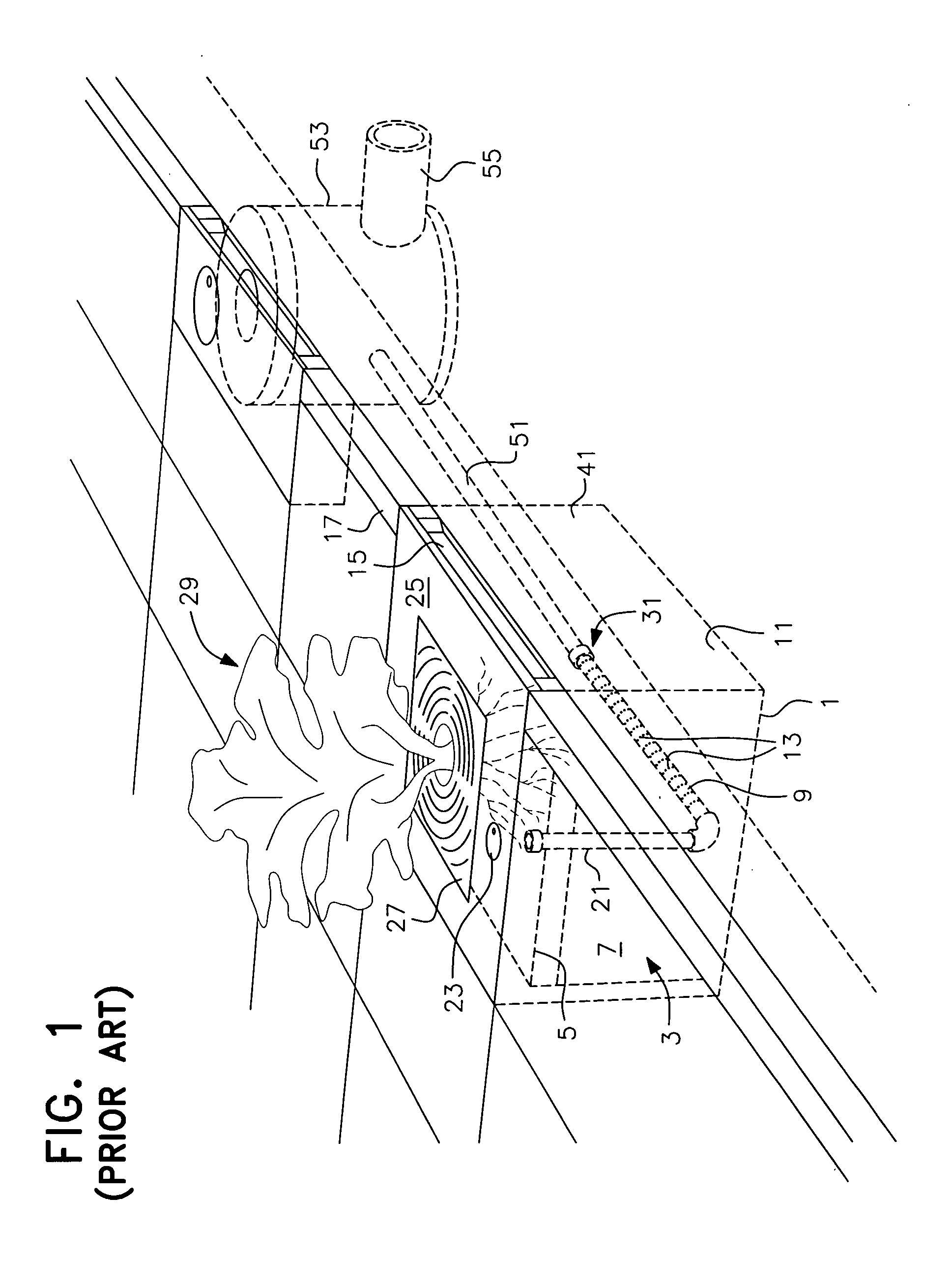
[0028]Referring now to the drawings and, specifically, FIG. 1, a prior art stormwater bioretention filtration system of the type disclosed in U.S. Pat. Nos. 6,277,274 and 6,569,321 (FIGS. 2 and 6, specifically) is depicted (hereinafter, the “Coffman patents”). This prior art system has been commercialized as the FILTERRA® stormwater bioretention filtration system by Americast, Inc. The prior art system includes a substantially water impermeable container 1, preferably of concrete, which holds filter media 3, including a mulch layer 5 overlying soil mixture 7 of the type described in the Coffman p...


PUM

PropertyMeasurementUnit
heightaaaaaaaaaa
heightaaaaaaaaaa
flow ratesaaaaaaaaaa

Abstract

A stormwater treatment system having a treatment container with two chambers, a treatment chamber and a bypass chamber. The bypass chamber includes an inlet for receiving stormwater. Disposed adjacent the inlet is an overflow tray secured to the walls of the bypass chamber. The tray includes an inlet opening for receiving the stormwater to be treated, and a discharge opening through the baffle wall that separates the two chambers for discharging stormwater that enters at low flow rates. The stormwater to be treated passes through the discharge opening into the treatment chamber where it is treated by the filter media. High flow rates will bypass the treatment chamber by overflowing a dam wall or weir defined by the overflow tray directly into the bypass chamber. Treated water from the treatment chamber passes through an underdrain pipe that enters into the bypass chamber. All water from the bypass chamber exits through pipe openings, preferably on each of three sides of the bypass chamber wall.

Description

RELATED APPLICATION[0001]This is a complete application of provisional application U.S. Ser. No. 61 / 282,366 filed Jan. 28, 2010, and hereby claims the priorities thereto to which it is entitled.BACKGROUND OF THE INVENTION[0002]1. Field of the Invention[0003]A stormwater filtration system having overflow / bypass capability forms the subject of the present invention. The stormwater filtration system includes a two chamber treatment container with a filter media that treats stormwater runoff through bioretention. Bioretention is the filtering of stormwater runoff through a terrestrial aerobic plant / soil / microbe complex to capture, remove, and cycle pollutants. The container includes a treatment chamber and a bypass chamber. A flow distribution overflow tray is positioned within the bypass chamber. The container receives stormwater through an inlet, such as a curb inlet, into the overflow tray that is positioned within the bypass chamber. Treatment flow is directed from the overflow tray...

Claims


Application Information

Patent Timeline
Patent Type & Authority Applications(United States)
IPC IPC(8): C02F1/00C02F103/00
CPCC02F1/00C02F2103/001B01D2221/12C02F2001/007
Inventor HOLTZ, JAMES FERGUSON
Owner AMERICAST
Why Eureka
Try Eureka