Dual-rotor motor and method of manufacturing the same

a dual-rotor motor and motor core technology, applied in the direction of dynamo-electric machines, magnetic circuit shapes/forms/construction, electrical apparatus, etc., can solve the problems of lack of joining strength, so as to ensure the stability of keeping weight balan

Inactive Publication Date: 2011-08-04
PANASONIC CORP
View PDF5 Cites 39 Cited by
  • Summary
  • Abstract
  • Description
  • Claims
  • Application Information

AI Technical Summary

Benefits of technology

[0012]Since the above method enables the individual tooth components fitted in the manner to protrude from both the inner peripheral side and the outer peripheral side of the yoke component, it ensures steadiness of keeping weight balance of ...

Problems solved by technology

This gives rise to a problem of lacking joining strength among the segmental components forming the teeth.
In other words, the stator core is prone to become damaged such as the teeth being broken or bent at their joined root portions when they are subjected to external forces during the process of winding coils and the like.
The method of separating the stator disclosed in the patent literature 2 also has the same problem of lacking the joining strength among the segmental components since the yoke has as many separate pieces as a nu...

Method used


Image

  • Dual-rotor motor and method of manufacturing the same
  • Dual-rotor motor and method of manufacturing the same
  • Dual-rotor motor and method of manufacturing the same

Examples


Embodiment Construction

[0028]Description will be provided hereinafter of an exemplary embodiment of the present invention with reference to the accompanying drawings.

Exemplary Embodiment

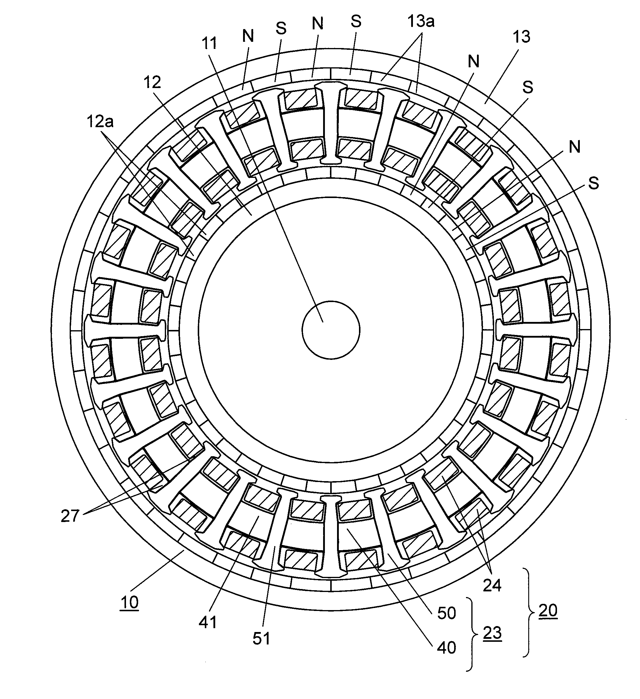
[0029]FIG. 1 is a schematic drawing showing a sectioned view of dual-rotor motor 10 according to this exemplary embodiment of the invention. FIG. 1 shows the sectioned view as observed in a longitudinal direction of a rotor shaft.

[0030]As shown in FIG. 1, dual-rotor motor 10 according to this exemplary embodiment comprises stator 20, inner rotor 12 and outer rotor 13. Stator 20 has coils 24 wound around stator core 23. Inner rotor 12 is disposed to an inner peripheral side of stator 20 in a rotatable manner, and outer rotor 13 is disposed around an outer peripheral side of stator 20 in a rotatable manner.

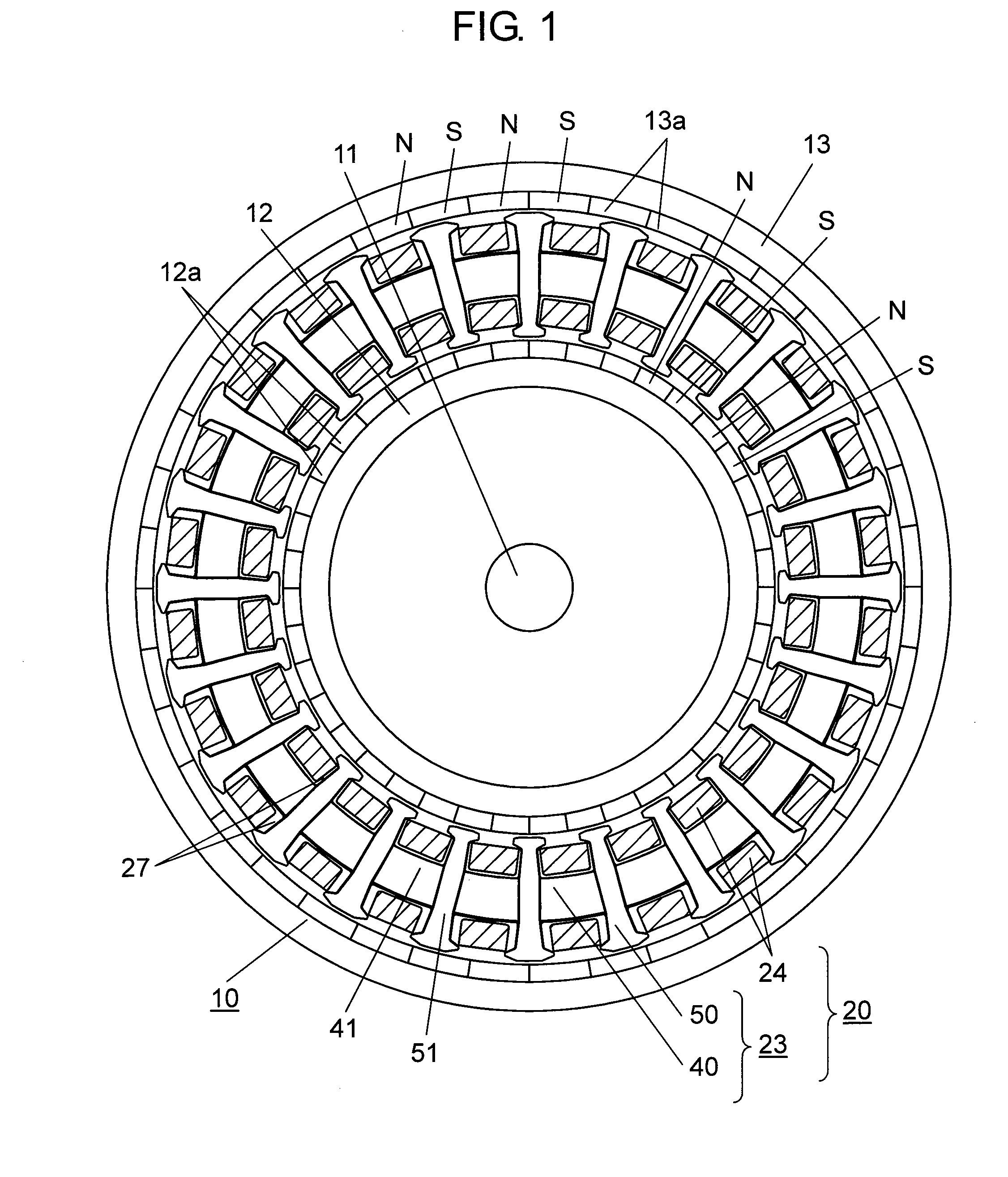
[0031]Stator core 23 includes annular yoke 40 and a plurality of teeth 50 that protrude from both the inner peripheral side and the outer peripheral side of yoke 40. There are void spaces defined as slots 27, each formed b...


PUM

PropertyMeasurementUnit
Shapeaaaaaaaaaa

Abstract

A dual-rotor motor provided with a stator having a stator core including a yoke, a plurality of teeth and a coil wound around the stator core, an inner rotor and an outer rotor, wherein the stator core includes an annular yoke component forming the yoke, and a plurality of tooth components forming the teeth. The stator core is made by fitting the tooth components individually into the annular yoke component in a manner that one ends of the tooth components protrude from the inner peripheral side of the annular yoke component and the other ends protrude from the outer peripheral side of the annular yoke component.

Description

TECHNICAL FIELD[0001]The present invention relates to a dual-rotor motor provided with a rotor at both inside and outside of a stator, and more particularly to a motor having a stator core made of a combination of segmental components.BACKGROUND ART[0002]There are some techniques heretofore made available, in which a stator core is made by combining segmental components prepared individually as separate pieces of the stator core. One example among those techniques hitherto disclosed is a method of separating a stator core into an annular yoke and a plurality of teeth (refer to patent literature 1, for instance). Also disclosed as another example is a method of separating a stator core into segmental pieces of a yoke configuration including a part of yoke and a tooth (refer to patent literature 2, for instance).[0003]The methods of separating the stator core as disclosed in these literatures have such advantages as easing the process of winding coils around the stator core, and impro...

Claims


Application Information

Patent Timeline
IPC IPC(8): H02K1/18H02K15/00H02K1/14
CPCH02K1/148Y10T29/49009H02K16/02
Inventor LI, HUYOSHIKAWA, YUICHIMURAKAMI, HIROSHIMATSUO, HIDEAKITASHIRO, YUICHIROMITAMURA, KOICHIINOUE, HIDETOTAJIMA, REIJIHATAYA, EIJI
Owner PANASONIC CORP
Why Eureka
Try Eureka